Installation
139
Mitel 415/430 as of R4.1
syd-0580/1.2 – R4.1 – 08.2016
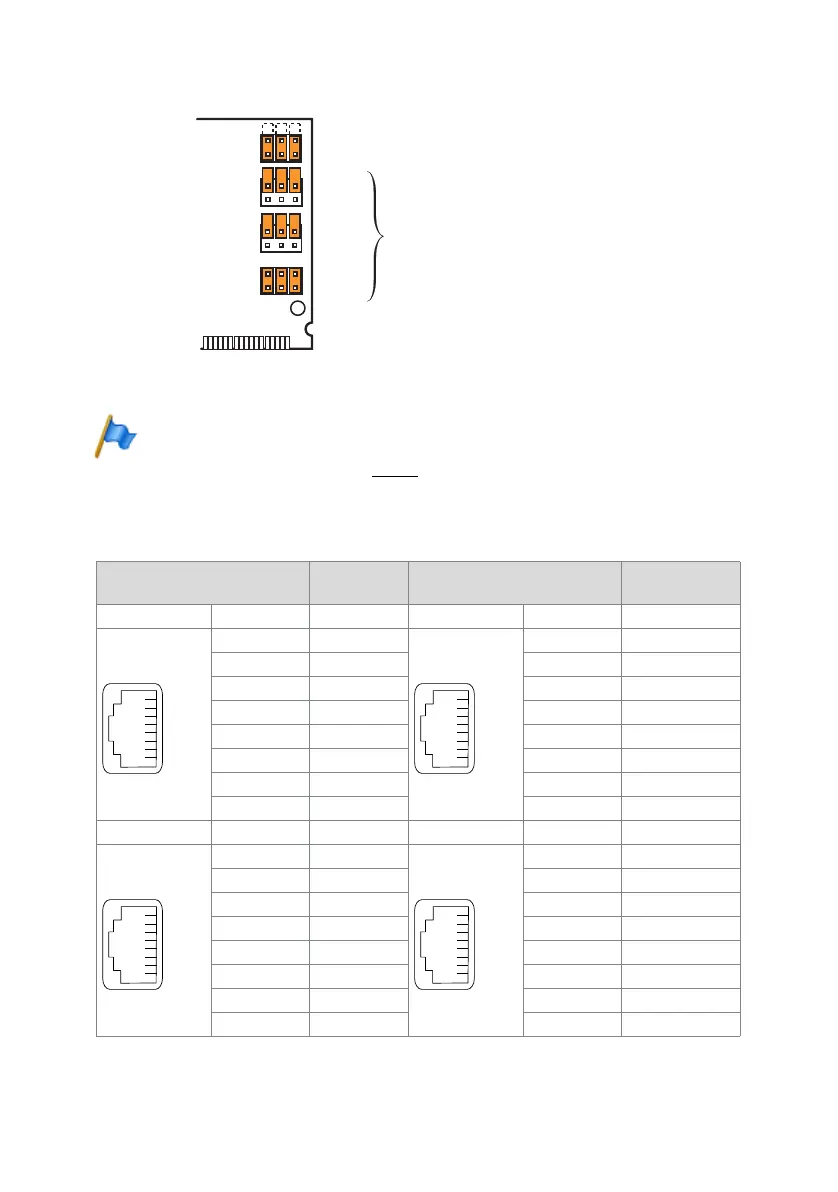
Fig. 63 Jumper configuration for connecting a door intercom
Note
If the options card is fitted on slot IC2 (Mitel 415 or slot IC4 (Mitel 430), the jumpers of Ports 1, 2
and 3 must be fitted as shown in Fig. 63.
Connection
Tab. 65 Connection in Slot 2 (Mitel 415) or Slot 4 (Mitel 430)
RJ45
Communica-
tion server
RJ45
Communication
server
Socket X1 Pin Signal Socket X3 Pin Signal
1– 1 –
2– 2 –
3 KT1 3 Tb (without DC)
4 TS2 4 Ta’ (with DC)
5 TS1 5 Tb’ (with DC)
6KT2 6Ta (without DC)
7– 7 –
8– 8 –
Socket X2 Pin Signal Socket X4 Pin Signal
1– 1 –
2– 2 –
3TO2 3 –
4IO4 4 –
5IO4 5 –
6TO1 6 –
7– 7 –
8– 8 –
Port 4
Port 3
Port 2
Port 1
IO4
TO
TS
KT
Congured for connecting a door intercom
free control input (marked ) or control
output (signied)