EasyManuals Logo

Mitsubishi 700 Series User Manual

Mitsubishi 700 Series
280 pages
To Next Page IconTo Next Page
To Previous Page IconTo Previous Page
Page #168 background imageLoading...
Page #168 background image
PROTOCOL-SPECIFIC INFORMATION
155
9
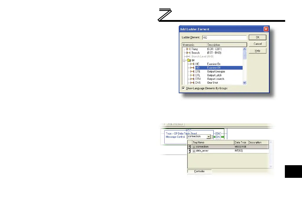
c) Select the “XIO” element in the Bit folder. Refer to
Figure 57.
d) Click OK.
4) Configure the MSG instruction.
a) Edit the “Message Control” field on the MSG
instruction to use the previously-created
“connection” tag. Refer to Figure 58.
b) Click the message configuration button (“…”) in
the MSG instruction. The “Message Configuration”
window will open. Refer to Figure 59.
c) “Configuration” tab settings:
i) Change the “Message Type” to “CIP
Data Table Read”.
ii) In the "Source Element” field, enter
the read tag you wish to access (refer
to section 9.2.9). In this example, we
will be reading a total of 25 registers
beginning at reg_201 (output
frequency).
Figure 57: Adding an XIO Element
Figure 58: MSG Instruction Tag Assignment

Table of Contents

Questions and Answers:

Question and Answer IconNeed help?

Do you have a question about the Mitsubishi 700 Series and is the answer not in the manual?

Mitsubishi 700 Series Specifications

General IconGeneral
Control MethodVector Control
Overload Capacity150% of rated current for 60 seconds
Protection FunctionsOvercurrent, Overvoltage, Undervoltage, Overheat, Short circuit
Communication OptionsRS-485, Profibus, Ethernet
Output Power Range0.4 kW to 630 kW
Cooling MethodForced air cooling (fan) (Varies by model)
Operating Temperature-10 to +50°C (Varies by model, may be derated at higher temperatures)
Storage Temperature-20 to +65°C
Humidity95% RH or less (non-condensing)
AltitudeUp to 1000 m above sea level (Derating may be required above 1000 m)
Enclosure RatingIP20
ModelFR-A700, FR-F700, FR-E700, FR-D700, FR-S700

Related product manuals