EasyManuals Logo

Mitsubishi 700 Series User Manual

Mitsubishi 700 Series
280 pages
To Next Page IconTo Next Page
To Previous Page IconTo Previous Page
Page #169 background imageLoading...
Page #169 background image
PROTOCOL-SPECIFIC INFORMATION
156
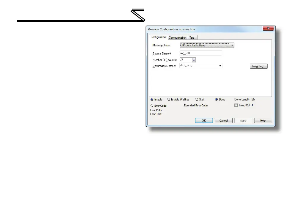
iii) Enter the Number Of Elements to
read. In this example, we will read
25 registers.
iv) For the Destination Element,
select “data_array.
d) “Communication” tab settings (refer to
Figure 60):
i) Enter the Path to the interface
card. A typical path is formatted
as
Local_ENB,2,target_IP_address”,
where:
Local_ENB is the name of the
1756-ENBx module in the
local chassis (we named ours
“EIP” in section 9.2.10),
2 is the Ethernet port of the
1756-ENBx module in the local chassis, and
target_IP_address is the IP address of the target node.
In our example, this path would be entered as “EIP,2,192.168.16.163”.
Figure 59: MSG Instruction Configuration

Table of Contents

Questions and Answers:

Question and Answer IconNeed help?

Do you have a question about the Mitsubishi 700 Series and is the answer not in the manual?

Mitsubishi 700 Series Specifications

General IconGeneral
Control MethodVector Control
Overload Capacity150% of rated current for 60 seconds
Protection FunctionsOvercurrent, Overvoltage, Undervoltage, Overheat, Short circuit
Communication OptionsRS-485, Profibus, Ethernet
Output Power Range0.4 kW to 630 kW
Cooling MethodForced air cooling (fan) (Varies by model)
Operating Temperature-10 to +50°C (Varies by model, may be derated at higher temperatures)
Storage Temperature-20 to +65°C
Humidity95% RH or less (non-condensing)
AltitudeUp to 1000 m above sea level (Derating may be required above 1000 m)
Enclosure RatingIP20
ModelFR-A700, FR-F700, FR-E700, FR-D700, FR-S700

Related product manuals