EasyManuals Logo

Mitsubishi 700 Series User Manual

Mitsubishi 700 Series
280 pages
To Next Page IconTo Next Page
To Previous Page IconTo Previous Page
Page #171 background imageLoading...
Page #171 background image
PROTOCOL-SPECIFIC INFORMATION
158
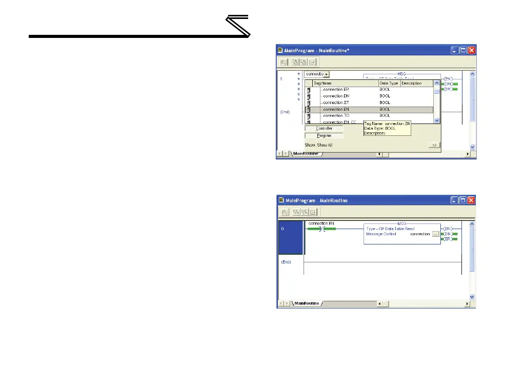
elements to allow triggering the MSG
instruction at a specific rate or under
specific conditions.
6) The program is now complete. Refer to
Figure 63.
7) Save, download and run the program.
a) To view the values of the registers being
read from the interface card, double-click
“Controller Tags” in the controller
organizer view.
b) Select the “Monitor Tags” tab and expand
the data_array tag.
c) 25 register values starting at register #201
are being continuously read from the
interface card and placed in the 25
sequential offsets of data_array starting at
the 0
th
offset.
Figure 62: Configure XIO Element
Figure 63: Complete Program

Table of Contents

Questions and Answers:

Question and Answer IconNeed help?

Do you have a question about the Mitsubishi 700 Series and is the answer not in the manual?

Mitsubishi 700 Series Specifications

General IconGeneral
Control MethodVector Control
Overload Capacity150% of rated current for 60 seconds
Protection FunctionsOvercurrent, Overvoltage, Undervoltage, Overheat, Short circuit
Communication OptionsRS-485, Profibus, Ethernet
Output Power Range0.4 kW to 630 kW
Cooling MethodForced air cooling (fan) (Varies by model)
Operating Temperature-10 to +50°C (Varies by model, may be derated at higher temperatures)
Storage Temperature-20 to +65°C
Humidity95% RH or less (non-condensing)
AltitudeUp to 1000 m above sea level (Derating may be required above 1000 m)
Enclosure RatingIP20
ModelFR-A700, FR-F700, FR-E700, FR-D700, FR-S700

Related product manuals