PROTOCOL-SPECIFIC INFORMATION
Figure 64 shows an example of three MSG instructions, one for reading and two for writing (the
inverter’s frequency command and command word). Note the addition of the en_xx_wr XIC elements.
The reason for the addition of these elements is that while reading from a remote device is often
continuously performed (monitoring), data is typically written to the remote device only when necessary
(i.e. when the value to write has changed). This conserves both network bandwidth and potentially
EEPROM lifespans on the target device. The en_xx_wr elements in this example, therefore, would
typically be replaced in an actual
application program by user-provided logic
that controls the conditions under which
write operations would be performed.
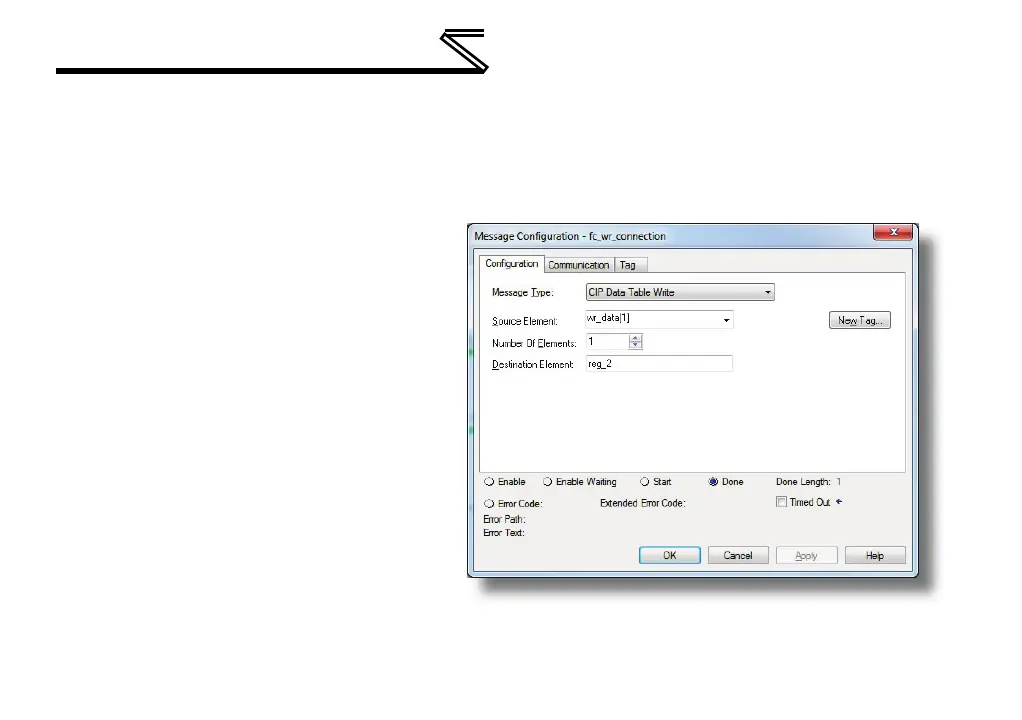
Figure 65 shows the configuration details of
the example fc_wr_connection MSG
instruction. Note that the chosen “Message
Type” is “CIP Data Table Write”, and that
this instruction will only be writing to one
inverter register: namely, the frequency
command (Destination Element is reg_2).
The Source Element in this case is the 2
nd
element (starting from index 0) of an INT
array tag named “wr_data”.
Note that when writing data via explicit
messaging, use caution to ensure that the
commanded registers are not also
Figure 65: MSG Configuration for Writing

 Loading...


