7 Operation
Maschinenfabrik Reinhausen GmbH 2019 1195163667/06 EN ETOS
®
IM
3. Press the Accept button to save the modified parameter.
If you use the optional function "Hot-spot calculation on 3 different windings
(W1, W2, W3)", you can use these parameters to set the circuit of the cur-
rent transformers. You can select the following options:
Option Description
Total current Measurement of differential current in 3-
phase grid.
Phase current Measurement of phase current in 3-phase
grid.
Table21: Current-transformer circuit W2/W3
To set the current-transformer circuit W2/W3, proceed as follows:
1. Go to Settings > Parameters > Transformer data > Current-trans-
former circuit W2/W3.
2. Select the desired option.
3. Press the Accept button to save the modified parameter.
7.4.2 Circuit examples for voltage transformers and current
transformers
Below you will find different examples of circuits for voltage transformers and
current transformers and the corresponding settings.
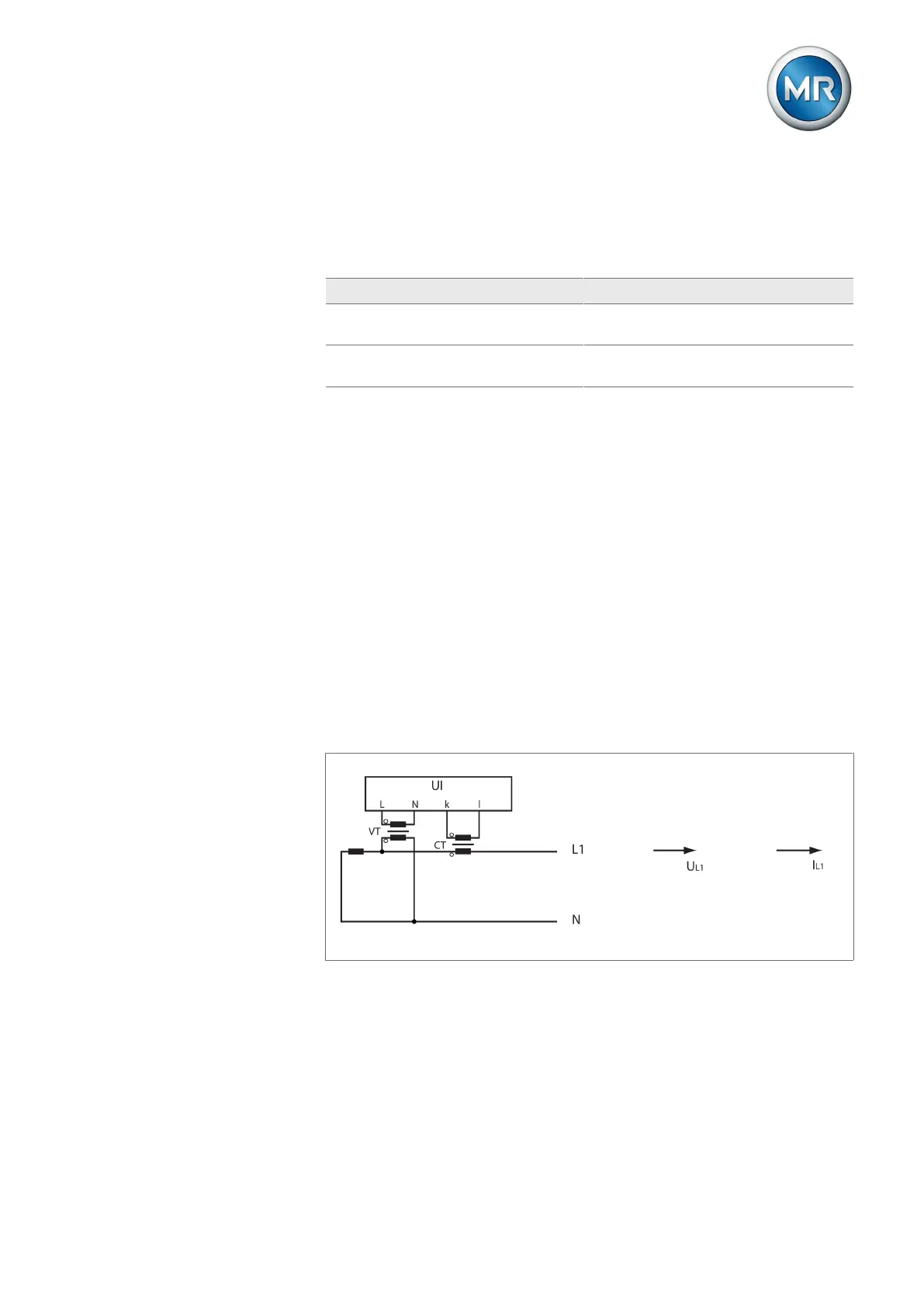
7.4.2.1 1-phase measurement
Circuit 1-A
▪ The voltage transformer VT is connected to the phase conductor and neu-
tral conductor.
▪ The current transformer CT is looped into the phase conductor.
▪ The voltage U
L1
and current I
L1
are in phase.
▪ The voltage drop on a phase conductor is determined by the current I
L1
.