5 Mounting
Maschinenfabrik Reinhausen GmbH 2019 615163667/06 EN ETOS
®
IM
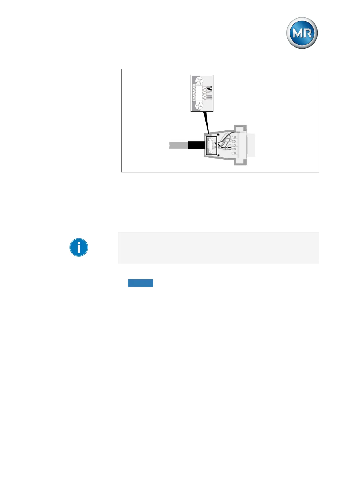
Figure43: Example of a soldered shielding on a plug housing
5.6.3 Notes on connecting to the MR sensor bus
The optionally available MR sensor bus function lets you connect digital and
analog sensors to the device over Modbus RTU. The MR sensor bus sup-
ports the connection of up to 31 sensors (Modbus slaves). The ISM® device
operates as the Modbus master.
Ensure that no other Modbus master is connected over the MR sensor bus.
Assign a unique Modbus address to each sensor you are connecting over
MR sensor bus. The MR sensor bus may experience errors if multiple sen-
sors are using the same Modbus address.
Observe the following notes for connecting the sensors:
▪ NOTICE! Damage to the device or sensor. Connect all of the sensors to
the potential equalization rail to avoid circulating currents over the MR
sensor bus.
▪ The MR sensor bus uses Modbus in a 2-wire configuration (2W). The 4-
wire configuration (4W) is not supported.
▪ They have to connect the sensors over a shielded line with 3 conductors
(D0, D1, Common). The data lines (D0, D1) have to be in twisted pairs.
Note the cable recommendation.
▪ Stubs of bus nodes for each node must be shorter than 20m.
▪ The CPU assembly contains a terminating resistor (120Ω) at the COM2
interface. Install another terminating resistor (120Ω, 0.5W) at the other
end of the bus.
▪ The CPU assembly contains a pull-up resistor and a pull-down resistor
(each of 680Ω in accordance with the Modbus specification). No addi-
tional pull-up/pull-down resistors are needed.