7 Operation
Maschinenfabrik Reinhausen GmbH 2019 2195163667/06 EN ETOS
®
IM
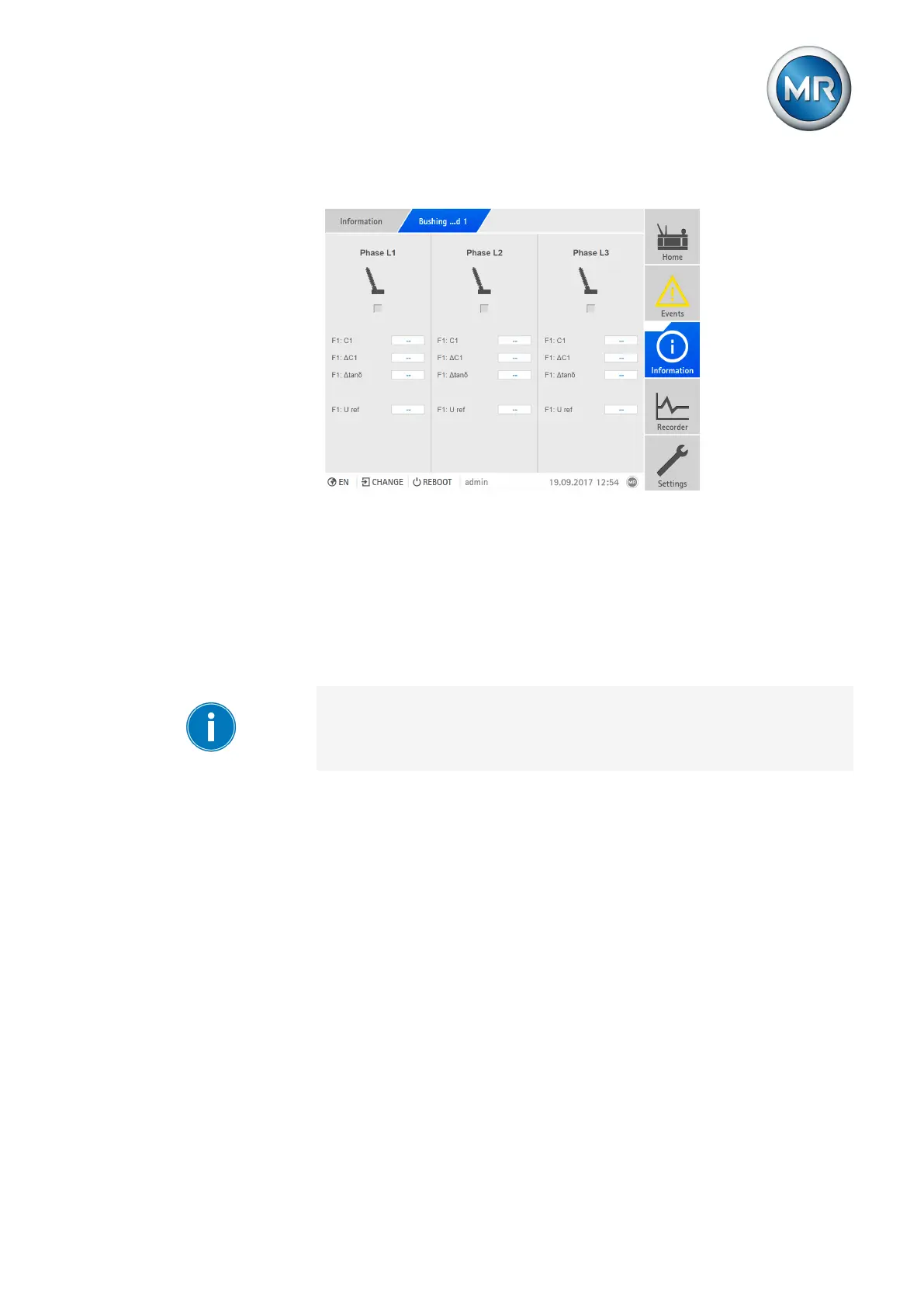
To display the state of the bushings, proceed as follows:
Figure164: Displaying the state of the bushings
► Go to Information > Bushing monitoring field1/field2.
7.16 MR sensor bus
The optionally available MR sensor bus function lets you connect digital and
analog sensors to the device over Modbus RTU. The MR sensor bus sup-
ports the connection of up to 31 sensors (Modbus slaves). The ISM® device
operates as the Modbus master.
Ensure that no other Modbus master is connected over the MR sensor bus.
Assign a unique Modbus address to each sensor you are connecting over
MR sensor bus. The MR sensor bus may experience errors if multiple sen-
sors are using the same Modbus address.
7.16.1 Configuring MR sensor bus
If you would like to use the MR sensor bus, you can configure the Modbus
protocol with the following parameters.
Note that the data transmission depends heavily on the number of sensors
and data points as well as the query rate and send delay time parameters.
Value changes can be transmitted on a delay lasting from several seconds
to a few minutes as a result.