7 Operation
Maschinenfabrik Reinhausen GmbH 2019 2315163667/06 EN ETOS
®
IM
If you have connected sensors over the MR sensor bus, you must select the
"Modbus" signal type for the desired functions. Observe the additional infor-
mation provided in the MR sensor bus [►Section 7.16, Page 219] section.
NOTICE
Damage to the device and sensors!
Incorrectly connected and configured analog inputs/outputs may result in
damage to the device and sensor.
► Follow information about connecting analog sensors.
► Configure analog inputs and outputs according to the connected sensors.
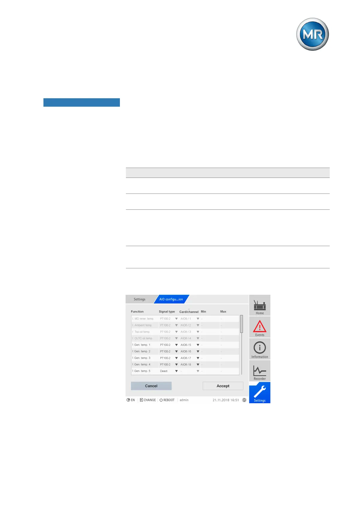
The following information is displayed in tabular form for configuring the ana-
log inputs and outputs. Grayed out elements cannot be changed.
Property Options
Function Function of the analog input (I: ...) or the analog output (O: ...). You
can adjust the designation.
Card/channel
1)
Select the slot and channel of the analog sensor. Note the connec-
tion diagram supplied.
Signal type Select signal type of analog sensor or deactivate analog output.
▪ 4...20mA
▪ PT100-2/3/4, PT1000-2/3/4
▪ Modbus (MR sensor bus)
Min/Max
1)
Set the minimum and maximum values of the sensor, e.g. with a
4...20 mA signal, the corresponding measured value for 4 mA and
the corresponding value for 20 mA.
Table60: Configuration of the analog inputs and outputs
1)
Not available with sensors connected over the MR sensor bus (Modbus).
Figure177: Configuring analog inputs/outputs