MultiSmart Installation & Operation Manual
Press Config to change additional settings for the level device. For Analog devices for example, the port it’s
connected to and the range (zero and span values) can be entered. For Probes and DuoProbes, the model
number, units and depth of well can be entered.
The main operator screen (the home page) displays a flashing INVALID indication in the level bar if the
primary level device is invalid and a backup level device is not configured.
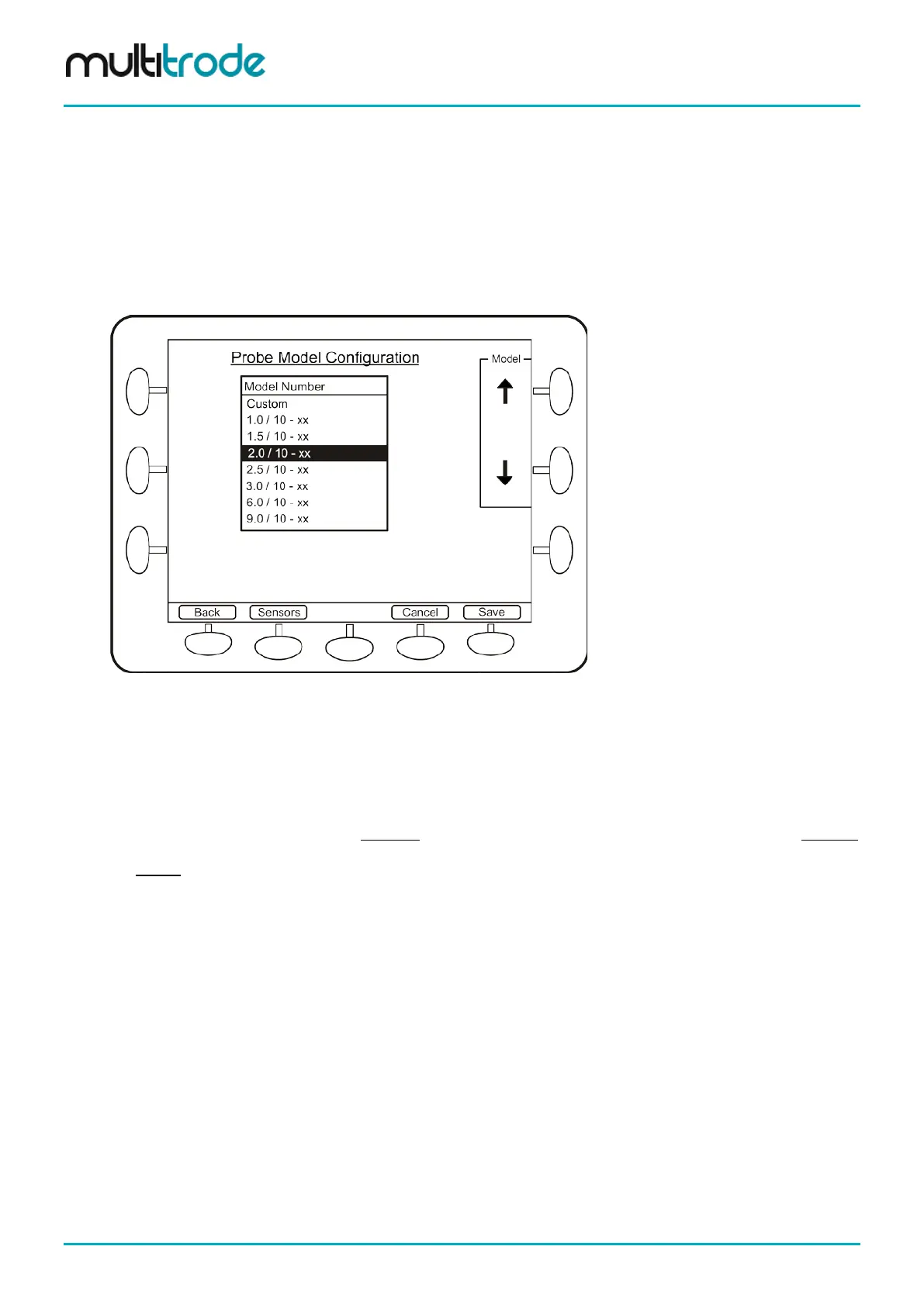
14.8.1 Probe Selection
If you have selected a Probe and pressed Config, the next screen, Probe Model Configuration lists all of
the standard models for you to select from.
Figure 112 – Probe Model Selection Screen
Select using the Model up and down arrows. If the units for the level display have not been changed from
percentage (0 -100%), then another screen is displayed (Probe Model – Extra Details). This screen
prompts the user to enter the depth of the well (and the units). Without this information, entering the probe
model has no meaning. Also, if the custom probe model is selected, the user can press the Modify button
displayed on the bottom right to display the Extra details screen, where details such as depth of well and
probe length can be entered using the units selected. Once Save is pressed, another prompt is displayed
asking if the setpoints should be rescaled. This rescaling (if answer “Yes”) ensures that the physical
activation and deactivation setpoints remain unchanged (strongly recommended). If the answer is “No”, then
the values of the existing setpoints remain unchanged but now represent depths in the well rather than points
along the probe. For example, a setpoint of 100% previously represented 100% on the probe but now
represents 100% of the well depth – i.e. a full well. An example follows.
Example of Probe Selection
The units have not been changed from the default percentage and the setpoint for lead pump activation is
50%, while lag pump activation is 60%. This means that the lead pump will start when the level is halfway up
the probe (not halfway up the well).
The user selects 1.0/10-xx (a 1m, 10-sensor probe) from the list and is now requested to enter the depth of
well and units. The well depth of 4m is entered. After the MultiSmart has reconfigured, the bar graph will only
show a quarter full when the top sensor on the probe is covered. This is because the probe is only 1m high in
a 4m well. The bar graph display can be changed by the parameter Show Full At in the first Level Device
configuration screen (section 14.8).
If the user does not select “Yes” to the option to Recalculate the setpoints, the lead activation setpoint will be
at 50% of the well - not 50% of the probe. If the user does select “Yes” – which is strongly recommended –
then the lead activation setpoint will be at 50% of the probe, or 0.5m.
Page 110 of 260 MultiSmart_IO_Manual_R20