MultiSmart Installation & Operation Manual
14.8.6 DuoProbe Level Sensor Configuration
Similar to the normal MultiTrode probe, a DuoProbe is comprised of ten (10) conductive sensors, with the
addition of a pressure transducer located at the end of the probe. (As for the standard probe, more than one
DuoProbe can be configured for a system, e.g. 2 wells, or a DuoProbe in primary and backup configuration).
For calibration purposes, a second pressure transducer is present in the MultiSmart to sense ground level
atmospheric pressure. The calibration process takes into account the pressure reading from the DuoProbe
and the atmospheric pressure measured by the sensor in the MultiSmart. To maintain accuracy, a
re-calibration can be triggered manually or by a timer. The recalibration process is inhibited when two or
more sensors are uncovered faster than a preset time, e.g. if the probe is manually raised too fast. (The
relevant parameter is the Level Change Time and has a default of 5s). The recalibration process is re-
enabled when two or more sensors are uncovered slower than the preset time.
There are hardware and firmware requirements which must be satisfied before the DuoProbe can be used as
the level device on a MultiSmart.
• Build Version - firmware installed must be version 2.20 or higher
• HW Version – the processor board must be version PCB40001r01 or higher
To confirm the versions are correct, navigate to:
and verify the Build and HW Versions.
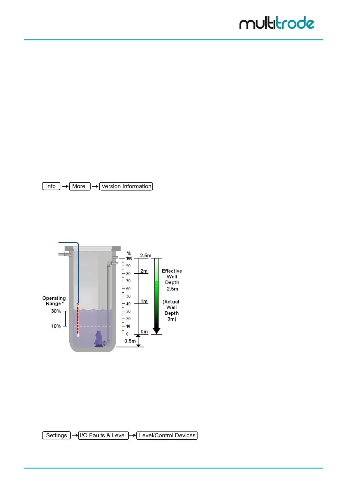
14.8.6.1 DuoProbe Placement – IMPORTANT Considerations
While the DuoProbe is capable of measuring the full depth of the well, MultiTrode recommends that the
probe is positioned such that the pumps operating range is within the probe range, i.e. the pump(s) activation
setpoint is below the top most sensor of the probe. See Figure 111. This best utilises the redundancy
feature of the DuoProbe should the analog pressure transducer fail.
* The operating range of the pump
sensor probe.
Should the analog pressure sensor fail, the
setpoints will shift slightly
so that they coincide with the
probe sensor immediately above
and the probe sensor immediately below
deactivation point.
Figure 114 – DuoProbe Positioned Within Operating Range of the Pump(s)
When the pressure transducer fails, a DuoProbe Error is triggered. If the DuoProbe is positioned such that
the activation setpoint is above the highest probe sensor, then when a DuoProbe Error occurs, the activation
setpoints are changed to the top most digital sensor level. This action is performed to ensure that the station
can continue to operate (although most likely over a different operating range).
14.8.6.2 Configuring the DuoProbe
To configure the DuoProbe, navigate to:
A simple wiring diagram for the DuoProbe interfacing with the MultiSmart is shown below.
MultiSmart_IO_Manual_R20 Page 113 of 260