MultiSmart Installation & Operation Manual
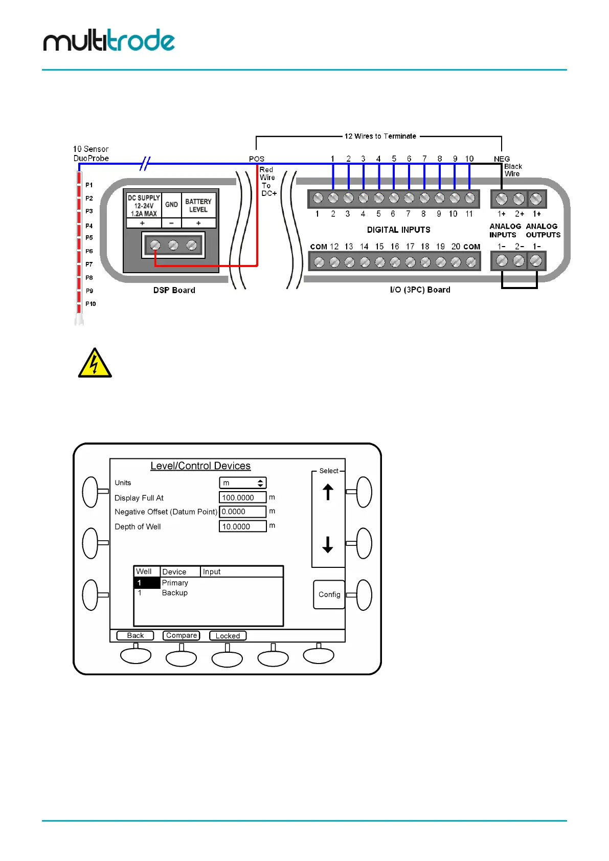
The negative terminal of the analog input (AIN 1-) is connected to a ground such as the GND on the DSP
board, or the negative input on the analog output (AOUT 1-), as illustrated below. The black wire is
connected to the positive terminal of the analog input (AIN 1+). The red wire is connected the positive DC
supply.
Figure 115 – DuoProbe Wiring to MultiSmart
e polarity to the
pressure sensor in the DuoProbe is incorrect, it may permanently damage the
sensor or the MultiSmart or both.
If the well depth is represented as percentage, then the Display Full At and Negative Offset (Datum Point)
options (with default values of 100 and 0) can be left unchanged. However if the well depth is specified as a
linear measurement, then select the appropriate Units and configure the Display Full At, Negative Offset
and the Depth of Well by highlighting the options and entering the new values. See the screen below.
Figure 116 – Well Parameters
Scroll down and select the Primary (or Backup) level device for which the DuoProbe requires configuration
and press Config.
Select DuoProbe 1 (or DuoProbe 2 if the first one is already assigned) and press Config. Select Save
changes & continue to the unsaved data prompt and then select the Restart Later option.
Select the DuoProbe length based on the model number and press Save. (The first number represents the
length of the probe in metres). The adjacent table below lists the various probe lengths in inches.
Page 114 of 260 MultiSmart_IO_Manual_R20