MultiSmart Installation & Operation Manual
5.4.1.5 Level Indication and Setpoints Display
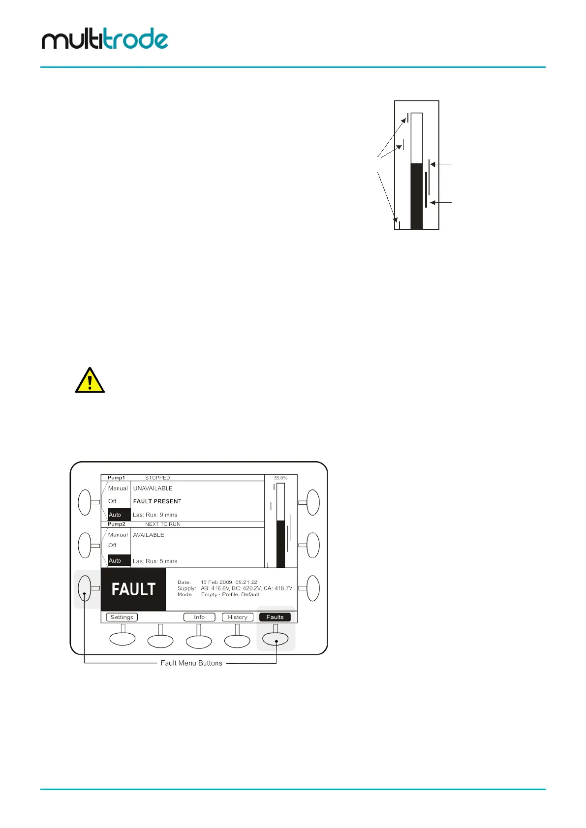
A bar graph is displayed next to the pumps and shows:
• Current liquid level
• Each pump’s activation and deactivation levels
• Level alarms that have been enabled
55.0%
Lag (Standby) Pump
activation and deactivation levels
Lead (Duty) Pump
activation and deactivation levels
Level Alarms
Figure 3 – Level Indication
5.4.1.6 Soft-keys
The buttons at the bottom of the screen are used to access the following areas:
• Settings - used to configure the MultiSmart pump station manager
• Info: displays full station and pump information
• History: shows alarms and event history
• Faults: shows details of current fault conditions
NOTE:
When the unit is controlling 5 or more pumps, a Next Pumps button also appears on the bottom line
allowing access to pumps 5 and 6, etc. This button is also present when the unit is configured for more
5.4.2 Faults / History
When a fault occurs, a large FAULT box is displayed at the bottom of the screen. At the same time, the fault
status changes to Fault Present.
Figure 4 – Fault Indication
The left Fault soft-key button flashes when a fault is present. Pushing this button (or the right Faults button)
displays a screen which details the fault. (Appendix A contains a description of all faults displayed).
Page 18 of 260 MultiSmart_IO_Manual_R20