S350 Series 24-Port (PoE+) and 48-Port Gigabit Ethernet Smart Managed Pro Switches
Configure Quality of Service User Manual187
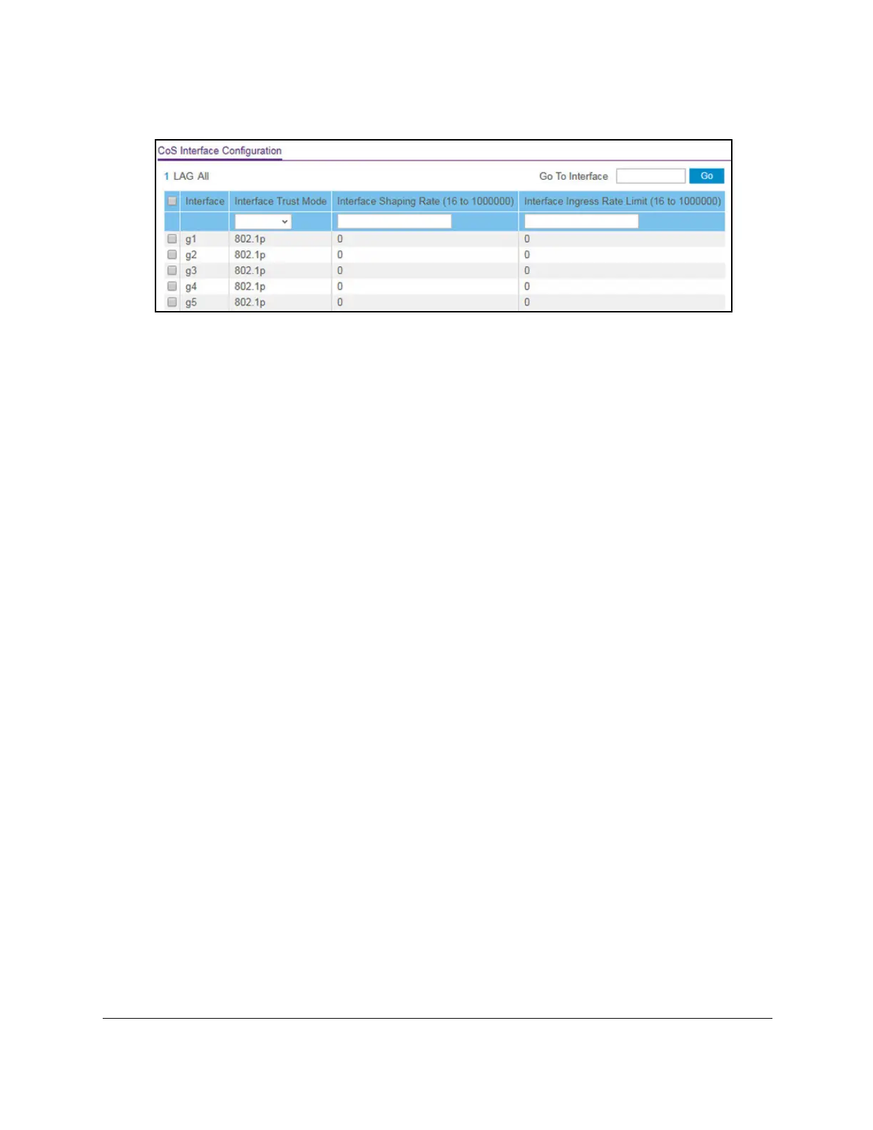
5. Select QoS > CoS > Advanced > CoS Interface Configuration.
6. Select whether to display physical interfaces, LAGs, or both by clicking one of the following
links above the table heading:
•1 (the unit ID of the switch). Only physical interfaces are displayed.
This is the default
setting.
• LAG
. Only LAGs are displayed.
• All. Both physical interfaces and LAGs are displayed.
7. Select one or more interfaces by taking one of the following actions:
• T
o configure a single interface, select the check box associated with the port, or type
the port number in the Go T
o Interface field and click the Go button.
• To configure multiple interfaces with the same settings, select the check box
associated with each interface.
• To configure all interfaces with the same settings, select the check box in the heading
row
.
8. From the
Interface Trust Mode menu, select one of the following trust mode options for
ingress traffic on the selected interfaces:
•
Untrusted. Do not trust any CoS packet marking at ingress.
• 802.1p. IEEE 802.1p specifies eight priority tags (p0 to p7). The QoS setting lets you
map each of the eight priority levels to an internal hardware priority queue. Models
GS324T and GS324TP support four hardware queues (0 to 3) and model GS348T
supports eight hardware queues (0 to 7). The default mode is 802.1p.
•
DSCP.
The six most significant bits of the DiffServ field are called the Differentiated
Services Code Point (DSCP) bits.
9. In the Interface Shaping Rate field, specify the maximum outbound transmission rate
bandwidth in kbps.
This setting is used to shape the outbound transmission rate in increments of 16 kbps in
the range from 16 to 1,000,000 kbps. This value is controlled independently of any
per-queue maximum bandwidth configuration. It is effectively a second-level shaping
mechanism.
The default value is 0. The value 0 means that the maximum is unlimited.
The expected shaping at egress interface is calculated as follows:
frameSize × shaping/(frameSize + IFG), where IFG (Inter frame gap) is 20 bytes,
frameSize is configured frame size, and shaping is configured traffic shaping.
 Loading...