A-153
Appendices
CJ2 CPU Unit Software User’s Manual
A-3 Auxiliary Area
App
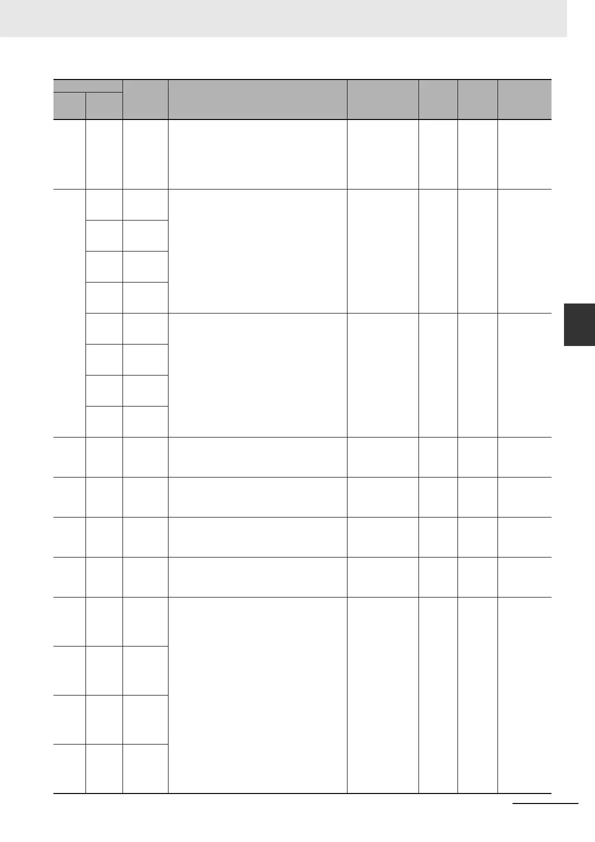
A-3-2 Read/Write Area (Set by User)
A530 --- Power Inter-
rupt Dis-
abled Area
Setting
Set to A5A5 hex to disable power interrupts (except the
Power OFF Interrupt task) between DI(693) and
EI(694) instructions.
A5A5 hex: Masking
power interruption
processing enabled
Other: Masking
power interruption
processing not
enabled.
Cleared Cleared ---
A531 A531.00 High-speed
Counter 0
Reset Bit
When the reset method is set to phase-Z signal + soft-
ware reset, the corresponding high-speed counter's PV
will be reset if the phase-Z signal is received while this
bit is ON.
When the reset method is set to a software reset, the
corresponding high-speed counter's PV will be reset in
the cycle when one of these bits is turned ON.
OFF to ON: Reset Retained Cleared ---
A531.01 High-speed
Counter 1
Reset Bit
A531.02 High-speed
Counter 2
Reset Bit
A531.03 High-speed
Counter 3
Reset Bit
A531.08 High-speed
Counter 0
Gate Bit
When one of these bits is turned ON, pulse inputs are
not counted and the PV of the corresponding high-
speed counter will not be changed.
When you turn OFF the bit, counting will be started
again and the PV of the high-speed counter will be
updated. If the reset method is set to phase-Z signal +
software reset and the corresponding High-speed
Counter Reset Bit (A531.00 to A531.03) is ON, then the
Gate Bit is not valid.
OFF to ON: PV held
ON to OFF: PV
updated
Retained Cleared ---
A531.09 High-speed
Counter 1
Gate Bit
A531.10 High-speed
Counter 2
Gate Bit
A531.11 High-speed
Counter 3
Gate Bit
A532 --- Interrupt
Counter 0
Counter Set
Value
This word is used for an input interrupt in counter mode.
Set the count until the interrupt task is executed. When
interrupt counter 0 counts the number of pulses set
here, interrupt task 140 will be executed.
0000 to FFFF hex Retained Cleared ---
A533 --- Interrupt
Counter 1
Counter Set
Value
This word is used for an input interrupt in counter mode.
Set the count until the interrupt task is executed. When
interrupt counter 1 counts the number of pulses set
here, interrupt task 141 will be executed.
0000 to FFFF hex Retained Cleared ---
A534 --- Interrupt
Counter 2
Counter Set
Value
This word is used for an input interrupt in counter mode.
Set the count until the interrupt task is executed. When
interrupt counter 2 counts the number of pulses set
here, interrupt task 142 will be executed.
0000 to FFFF hex Retained Cleared ---
A535 --- Interrupt
Counter 3
Counter Set
Value
This word is used for an input interrupt in counter mode.
Set the count until the interrupt task is executed. When
interrupt counter 3 counts the number of pulses set
here, interrupt task 143 will be executed.
0000 to FFFF hex Retained Cleared ---
A536 --- Interrupt
Counter 0
Counter
Present
Value
Contain the PVs of the interrupt counters for input inter-
rupts in counter mode. In incremental mode, the count
is incremented one count at a time until it matches the
counter set value, at which time it returns to 0. In decre-
mental mode, the count is decremented one count at a
time from the set value until it reaches 0, at which time
it returns to the set value.
0000 to FFFF hex Retained Cleared ---
A537 --- Interrupt
Counter 1
Counter
Present
Value
A538 --- Interrupt
Counter 2
Counter
Present
Value
A539 --- Interrupt
Counter 3
Counter
Present
Value
Address
Name Function Settings
Status
after
mode
change
Status at
startup
Write timing/
Related flags,
settings
Words Bits