92
Settings Section 3-1
3-1 Settings
3-1-1 Wiring
• Connect a two-conductor twisted-pair shielded cable to the Analog Input
Unit.
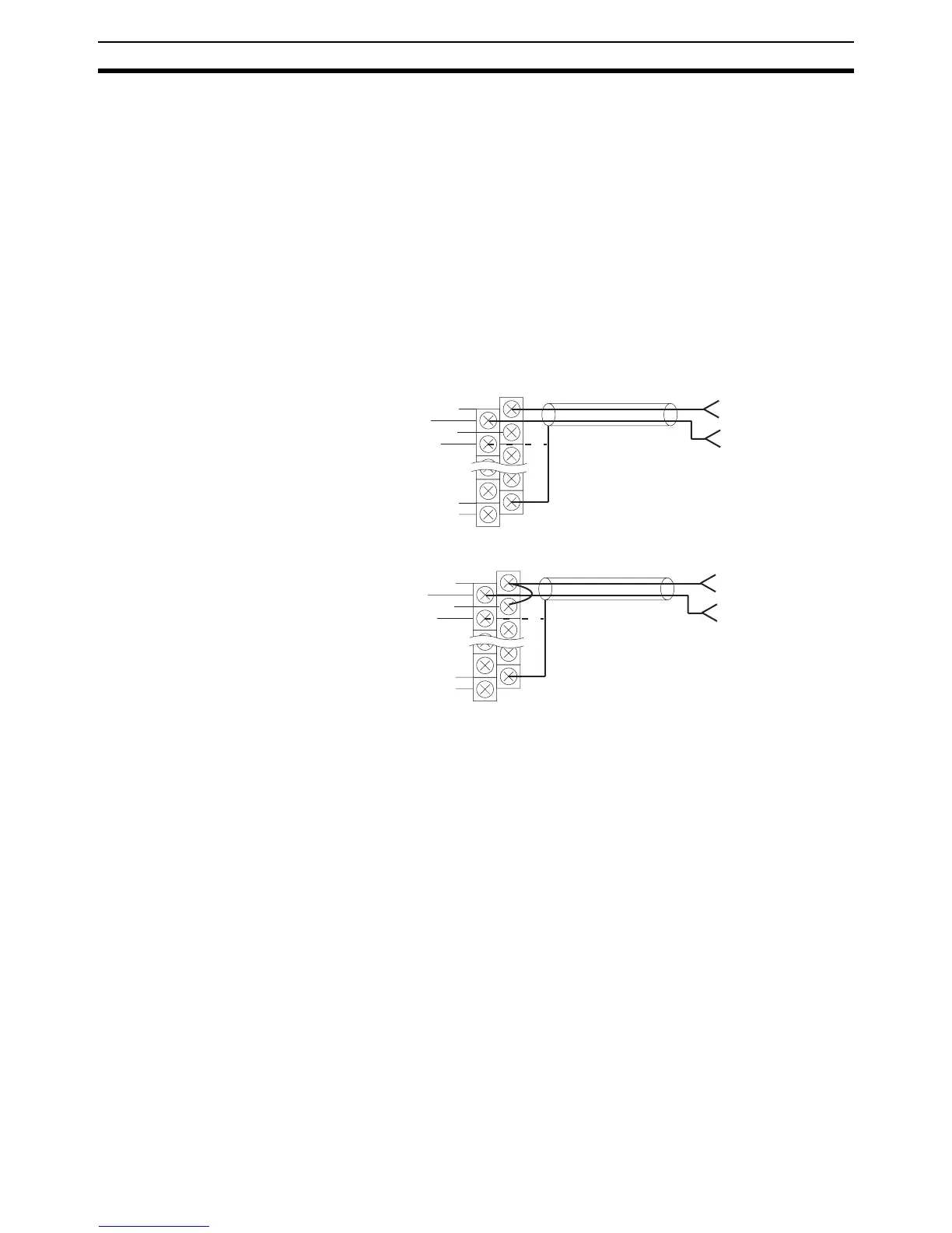
• The input terminals of the Analog Input Unit, to which the two-conductor
twisted-pair shielded cable is connected, vary with the input range as
shown in the following illustrations. In some environments, the shielded
wire of the two-conductor twisted-pair cable should be connected to the
COM terminal instead of the FG terminal of the Analog Input Unit so that
the Analog Input Unit will not be influenced by external noise.
• The COM terminal is internally connected to the analog 0-V terminal of
the Analog Input Unit.
Voltage Input
Current Input Short-circuit the V+ and I+ terminals for current input.
3-1-2 Wiring Precautions
In order to prevent noise interference, note the following when wiring the Ana-
log Input Unit:
• Do not install power lines or high-tension lines along in close proximity to
the Analog Input Unit’s input lines.
• When connecting an inductive load such as a relay, solenoid, or electro-
magnet valve to the Analog Input Unit, be sure to insert a surge absorp-
tion diode or surge absorber to the load circuit as shown in the following
examples. The surge absorption diode or surge absorber must be as
close as possible to the inductive load in the load circuit. The withstand
voltage of the surge absorption diode must be at least five times as large
as the circuit voltage.
V–
I+
COM
FG
V+
FG
0 V
0 V
V–
I+
COM
FG
V+
FG