179
System Configuration Section 1-2
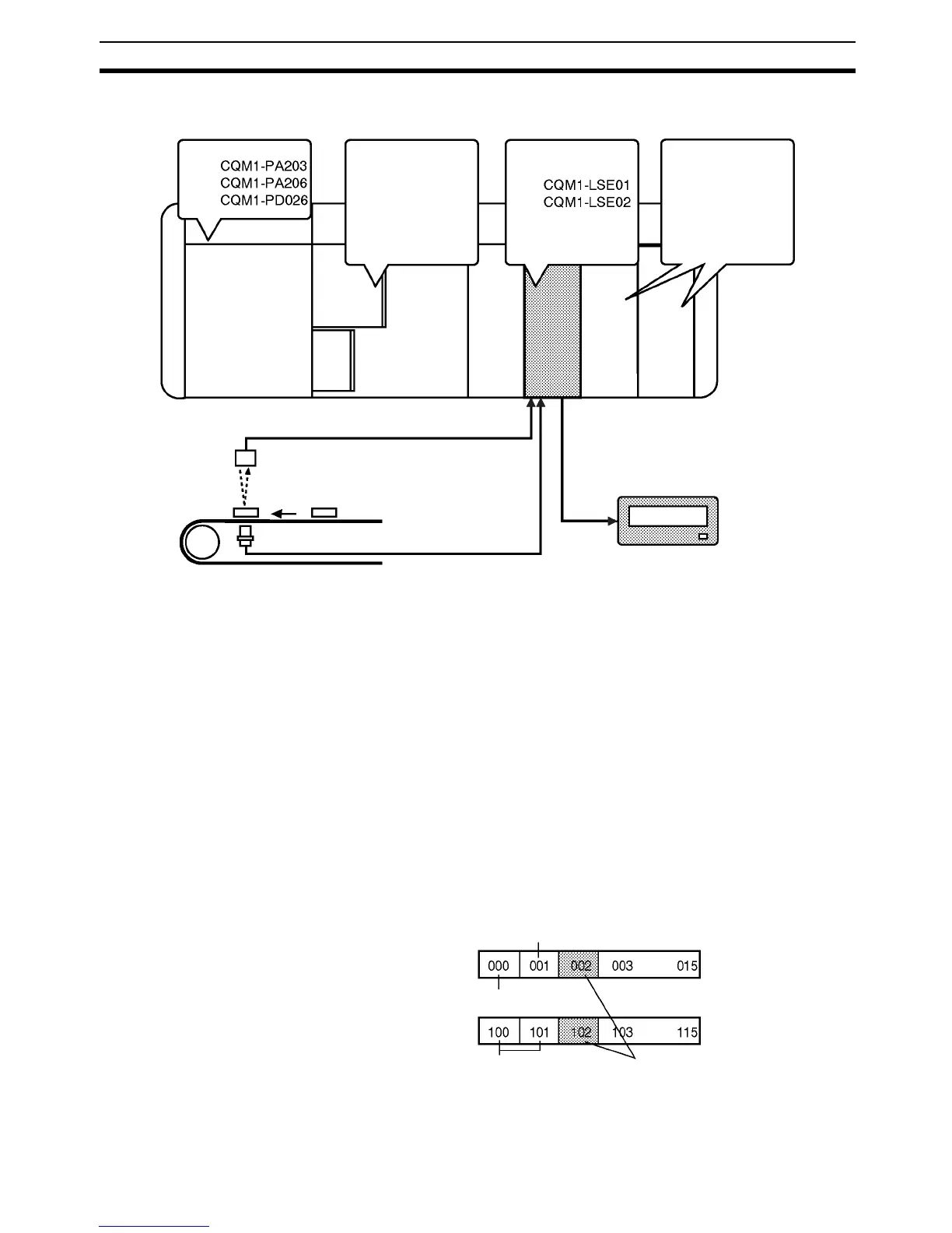
1-2 System Configuration
• Use the Programming Console to write its initial values to the Unit.
• The Unit needs zero input and zero reset input for forced zero.
• The CQM1-LSE01 does not have monitor output.
Word Number The word allocations for a CQM1H/CQM1-series Dedicated I/O Unit are as
follows.
Input: 001 to 015
Output: 100 to 115
The Unit uses a single input word and single output word. The CQM1-LSE01,
which is not provided with the monitor output function, also uses a single out-
put word.
Words are allocated in left-to-right order to the CQM1H/CQM1-series Dedi-
cated I/O Units mounted to the PC. For example, if an Input Unit that occupies
one word, an Output Unit that occupies two words, and the CQM1-LSE01/
LSE02 are mounted to the PC and if the Input Unit and Output Unit are
located to the left of the CQM1-LSE01/LSE02, the input and output word
numbers of the CQM1-LSE01/LSE02 will be 002 and 102 respectively.
Power Supply
CQM1H/CQM1-series
CPU
Linear Sensor
Interface
Other Units
Sensor input
(V INPUT/I INPUT)
Timing input
(T/G)
Monitor output
(OUTPUT)
to
to
Input word
Output word
Input Unit located on the left side
CPU
Output Unit located
on the left side
CQM1-LSE01/LSE02