EasyManuals Logo

Omron CQM1 User Manual

Omron CQM1
312 pages
To Next Page IconTo Next Page
To Previous Page IconTo Previous Page
Page #211 background imageLoading...
Page #211 background image
192
Nomenclature Section 3-1
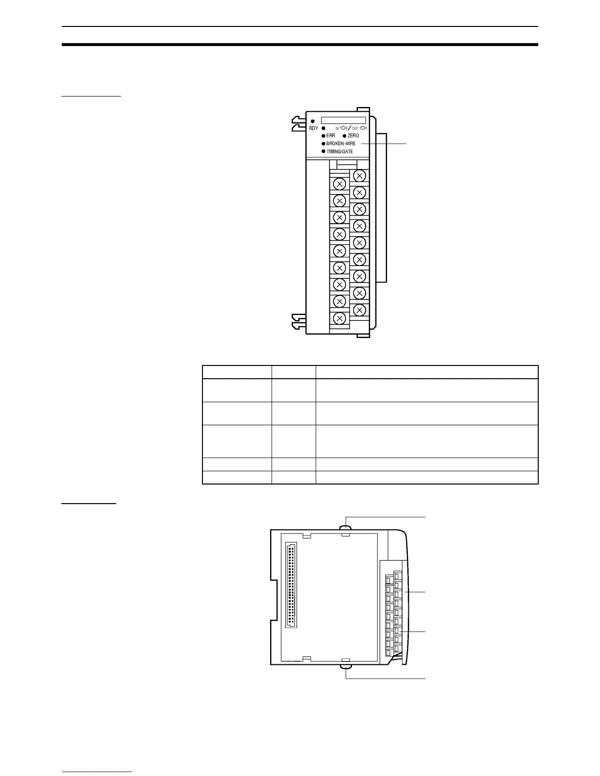
3-1 Nomenclature
Front View
Indicators
Side View
Indicators
Name Color Function
RDY Green Lit when the Linear Sensor Interface Unit is ready for
use.
ERR Red Lit when an internal error, such as IC malfunctioning,
occurs.
BROKEN-WIRE Red Lit when 1- to 5-V or 4- to 20-mA input to the Unit is dis-
connected. This indicator cannot be used to detect the
disconnection of ±9.999- or ±5-V input.
TIMING/GATE Orange Lit when TIMING or GATE input to the Unit is ON.
ZERO Orange Lit when the forced zero function is effective.
Slide lock
Cover
Terminals
Slide lock

Table of Contents

Questions and Answers:

Question and Answer IconNeed help?

Do you have a question about the Omron CQM1 and is the answer not in the manual?

Omron CQM1 Specifications

General IconGeneral
ModelCQM1
I/O CapacityUp to 256 I/O points
Programming LanguageLadder Logic
Timer/Counter128 timers/counters
Operating Temperature0 to 55°C
Humidity10 to 90% RH (non-condensing)
Power Supply24 VDC or 100-240 VAC
Communication PortsRS-232C
Memory Capacity3.2K words
Instruction SetBasic and advanced instructions
MemoryRAM (battery-backed)
Program Memory3.2K words
Storage Temperature-20 to 75°C

Related product manuals