74
SYSMAC BUS Cable Connections Section 3-1
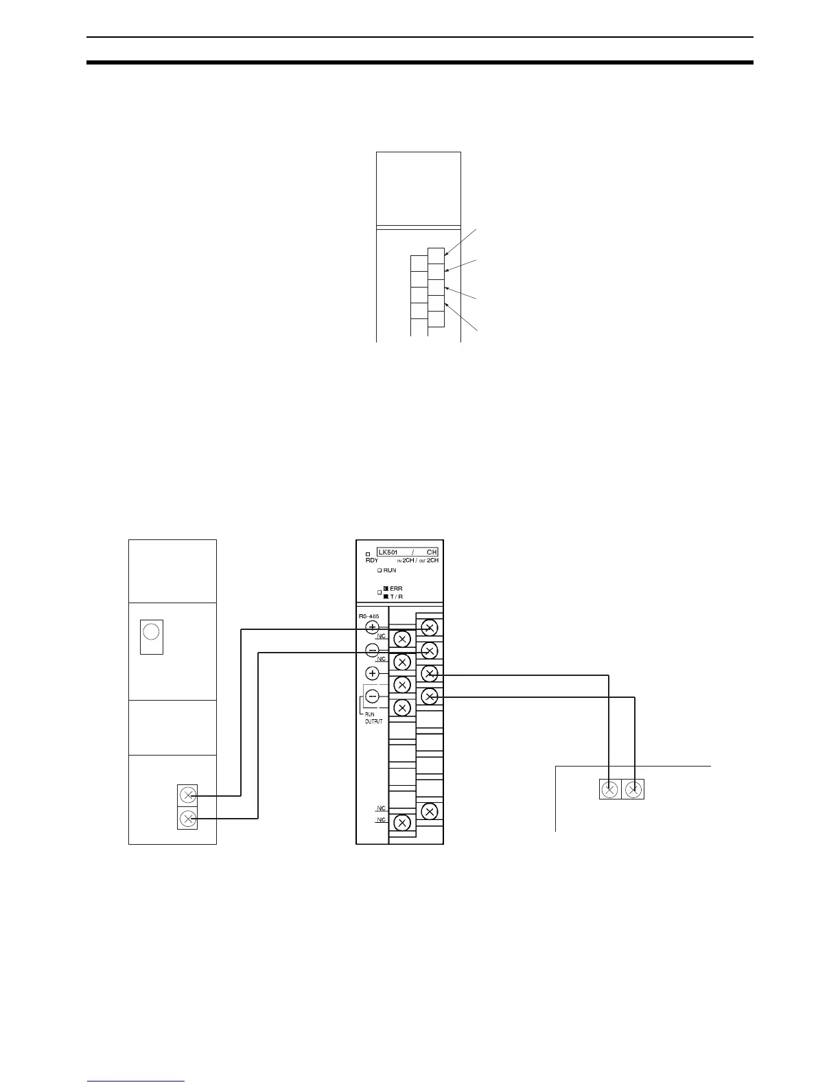
3-1 SYSMAC BUS Cable Connections
Connect VCTF 0.75 x 2 C SYSMAC BUS cables to the CQM1-LK501 I/O LInk
Unit as shown in the following.
Note Nothing is connected to these terminals in the case of the terminator.
Connect the Master and Slaves as described in the following.
The positive terminal of the Master must be connected to the positive terminal
of the Slave and the negative terminal of the Master must be connected to the
negative terminal of the Slave, and between Slaves, the positive terminals
must be connected together and the negative terminals must be connected
together as shown in the above diagram.
The end Slave of the system must be the terminator of the system. Any other
Slave must not be the terminator.
Note 1. Connect the terminals with crimp-style terminals and M3 terminal screws
that are also used for CQM1H/CQM1 I/O Units.
2. Terminals B
0
and B
2
are short-circuited internally. Terminals B
1
and B
3
are
also short-circuited internally.
3. Be sure to turn all the Slaves on before turning on the Master. Any Slave
turned on after the Master is turned on will not be recognized by the Mas-
ter.
Connect the positive signal line
from the Master.
Connect the negative signal line
from the Master.
Connect the positive signal line to
the next Slave (see note).
Connect the negative signal line to
the next Slave (see note).
A
0
A
1
A
2
A
3
B
0
B
1
B
2
B
3
B
4
Remote I/O Master
CQM1-LK501 I/O LInk Unit
Other Slave
Terminator setting
+
–
+
–
+
–
+–