70
Nomenclature Section 2-1
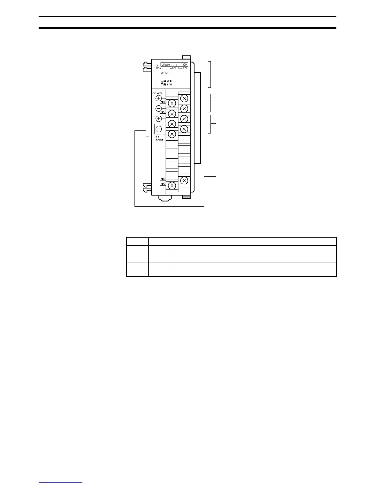
2-1 Nomenclature
Indicators
The terminator setting switch and DIP switch are located under the terminal
board.
The ERR T/R indicator is lit only when there is an error is and will flash auto-
matically when the transmission returns to normal.
Indicators (see table)
Transmission terminal 2
Transmission terminal 1
Operation output terminals
Operation output terminals must be short-cir-
cuited if transmission is normal when the Master
is in operating mode. These terminals are used to
retrieve signals from the Master in operation.
Terminal screws: M3
Note To satisfy the EC directives (low-voltage
directives), provide reinforced insulation
or double insulation for the power supply.
(refer to 3-1 SYSMAC BUS Cable
Connections.)
(refer to 3-1 SYSMAC BUS Cable
Connections.)
Name Color Function
RDY Green Lit while the CQM1H/CQM1 is supplied with power.
RUN Green Lit when the Master is in operating mode.
ERR T/
R
Red Lit when there is a transmission error. Flashes during normal trans-
mission.