20
Connections to B7A Link Terminals Section 3-1
3-1 Connections to B7A Link Terminals
3-1-1 Recommended Cables
The B7A Interface Unit can be connected to the input and output B7A Link
Terminals using the following cables.
Standard Transmission Delay-time Type
Cabtire Cable Use a VCTF 0.75 x 3 C cabtire cable (100 m max.) if a power supply is shared
and a VCTF 0.75 x 2 C cabtire cable (500 m max.) if power is supplied inde-
pendently.
Rapid Transmission Delay-time Type
Shielded Cable Use a 0.75 x 3 C shielded cable (50 m max.) if a power supply is shared and a
0.75 x 2 C shielded cable (100 m max.) if power is supplied independently.
!Caution If shielded cable is not used for the high-speed transmission delay-time Link
Terminal, the transmission distance is not to exceed 10 m regardless of
whether power supply is shared or wired separately.
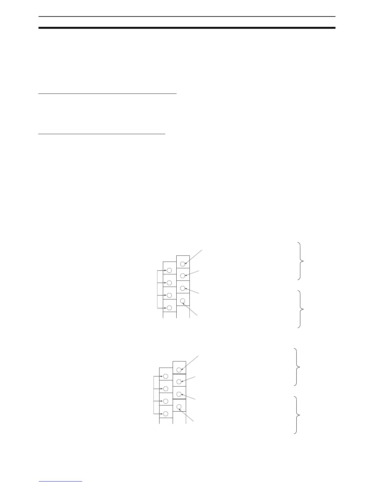
3-1-2 Connecting Terminals
Connect the input and output B7A Link Terminals to the B7A Interface Unit via
the following terminals using crimp-style terminals used for CQM1H/CQM1 I/
O Units.
CQM1-B7A21
CQM1-B7A13
Unused
Connect to the SIG terminal of
the output B7A Link terminal.
Connect to the negative power supply ter-
minal of the output B7A Link Terminal.
Connect to the SIG terminal of
the input B7A Link Terminal.
Connect to the negative power supply ter-
minal of the input B7A Link Terminal.
A
0
A
1
A
2
A
3
B
0
B
1
B
2
B
3
Word m
Word n
Unused
Connect to the SIG terminal of
the input B7A Link terminal.
Connect to the negative power supply ter-
minal of the input B7A Link Terminal.
Connect to the SIG terminal of
the input B7A Link Terminal.
Connect to the negative power supply ter-
minal of the input B7A Link Terminal.
A
0
A
1
A
2
A
3
B
0
B
1
B
2
B
3
Word n
Word n + 1