36
Nomenclature Section 2-1
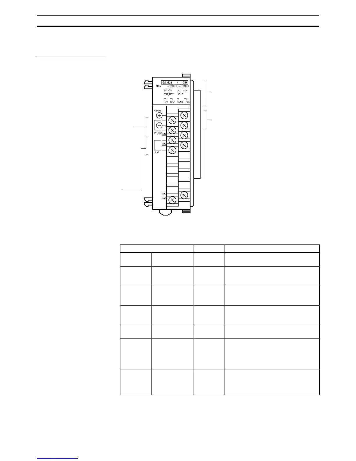
2-1 Nomenclature
CQM1-G7M21 Master
Front View
Indicators
Terminal screws: M3
(Optimum tightening torque: 0.5 N • m)
Transmission terminal
For connection of transmission
cable to Expansion Master or
Slave.
Indicators (see following table)
ALM output terminals
Terminals shorted if an error oc-
curs in the output of a unit with
error detection function
(G730-ROC04-A).
Transmission Ready terminals
Terminals shorted while in trans-
mission status with power on.
Read signal at CPU and confirm
transmission ready status be-
fore enabling data.
The output from these ter-
minals linked to ON/OFF status
of the T/R RDY indicator.
+
–
(Refer to 3-2 External Output
Connection Cables)
(Refer to 3-2 External Output
Connection Cables)
Refer to 4-2 Handling Power On.
(Refer to 3-1 Transmission Cables)
Name Color Function
RDY Unit Ready Green Lit when power is on and if CQM1H/
CQM1 recognizes a Master.
IN 1CH IN Mode Orange Lit while number of inputs set to 1 word
(16 points). Not lit when set to 2 words
(32 points).
OUT 1CH OUT Mode Orange Lit while number of outputs set to 1
word (16 points). Not lit when set to 2
words (32 points).
T/R RDY Transmission
Ready
Green Lit while in transmission status with
power on. Not lit while in transmission
error.
HOLD HOLD Setting Orange Lit while DIP switch set to HOLD (data
held when a transmission error occurs).
T/R Transmitting Red Flashes while searching for terminator
or during transmission with power
turned on. Lit when there is a transmis-
sion error. Not lit when there is an error
in the Master.
END Terminator Red Lit when the power is turned on. Goes
out when the terminator is found.
Flashes when multiple terminators are
present.