196
Mounting and Wiring Section 4-1
4-1 Mounting and Wiring
Mounting Refer to the CQM1H Operation Manual (W363) or the CQM1 Operation Man-
ual (W226) before mounting this Unit to the PC.
Wiring Refer to 3-2 Terminals for the wiring of the terminals.
!Caution
• Make sure that the polarity of each input line connecting to the terminals
is correct.
• It is possible that the terminal block may become disconnected from the
Unit. After the terminals are wired, make sure that the terminal block is
properly connected to the Unit.
Connection Terminals Connect each input line to the terminal using a solderless terminal.
Do not tighten any screw of the terminals to a torque exceeding 0.5 N • m.
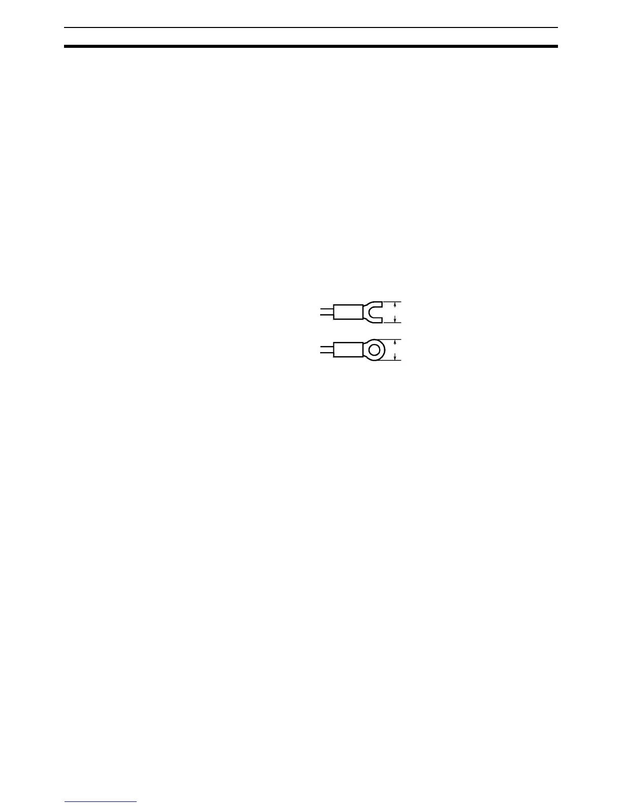
Use either of the following types of M3 solderless terminals for the input lines
connecting to the terminals.
Crimp Connectors Crimp connectors for wiring should be less than 6.2 mm wide (M3), and the
wire should be AWG22 to 18 (0.25 to 1.65 mm
2
).
6.2 mm max.
6.2 mm max.