107
Appendix B
Troubleshooting
Analog Input Unit
Analog Power Supply Unit
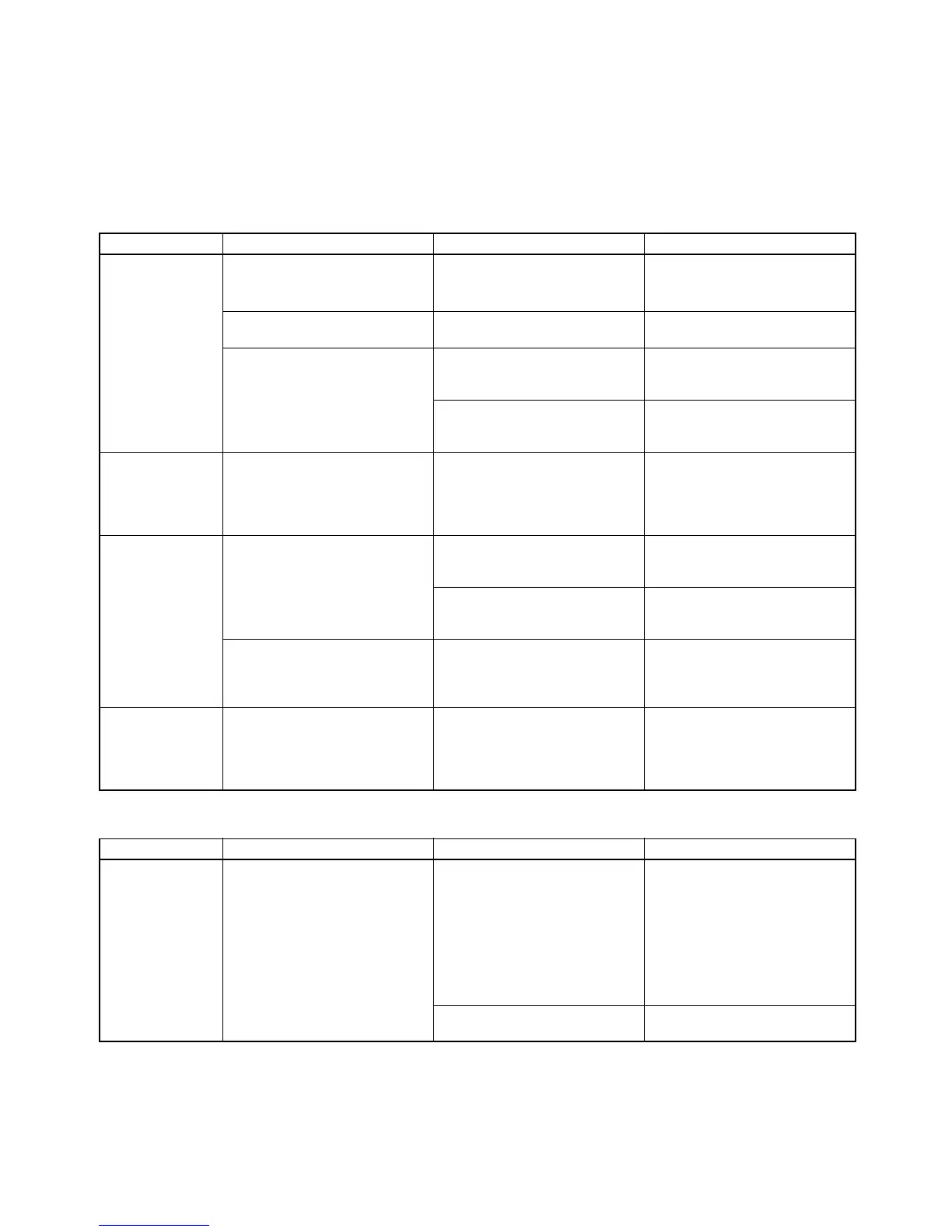
Kind of error Phenomenon Cause Remedy
Indicator The RDY indicator is not lit. 1. The Unit is not connected
properly.
2. No end cover is attached.
Refer to the CQM1H/CQM1
Operation Manual and reset the
Analog Input Unit.
The ERR indicator is lit. The DIP switch is set to prohibit
the conversion of all inputs.
Refer to 2-1 Nomenclature and
set the DIP switch properly.
The BROKEN WIRE indicator is
lit.
An input set to a range of 1 to 5
V or 4 to 20 mA is disconnected.
Check the wiring, terminal
board, input voltage, and input
current.
Unused analog input is set to a
range of 1 to 5 V or 4 to 20 mA.
Set the unused analog input to
any other range or set to prohibit
conversion.
No. of words The Analog Input Unit can be
allocated to two words only or
allocated to four words.
The DIP switch setting is incor-
rect.
The DIP switch setting can be
monitored with the 2 CH and 4
CH indicators. Check whether
the setting is proper. If not, set
the DIP switch properly.
Conversion data The conversion data of the Ana-
log Input Unit does not change
even if the input voltage or cur-
rent is changed.
The power cable is not con-
nected to the Analog Power
Supply Unit.
Connect the power cable.
The voltage or current input is
not within the range that has
been set.
Check the input voltage or cur-
rent or the range that has been
set.
The conversion data of the Ana-
log Input Unit changes slowly
when the input voltage or current
is changed.
The mean value processing
function is working.
Set the mean value processing
switch properly.
I/O Unit over The CPU has an I/O Unit over
error.
The total number words used by
the Units connected exceed the
maximum available words of the
CPU.
Each Analog Input Unit uses
four or two words. Check if the
total number of words are
exceeding the maximum avail-
able words of the CPU.
Kind of error Phenomenon Cause Remedy
LED The P/S (P/S1, P/S2) indicator is
not lit.
The power supply cable of the
Analog Input Unit is not con-
nected to the Analog Power
Supply Unit.
Connect the power supply cable
to the Analog Power Supply
Unit. Turning on the Analog
Power Supply Unit will not cause
the P/S (P/S1, P/S2) indicator to
be lit if the power supply cable of
the Analog Input Unit is not con-
nected to the Analog Power
Supply Unit.
Power is not supplied to the sys-
tem.
Supply power to the system.