143
Switch Settings Section 2-2
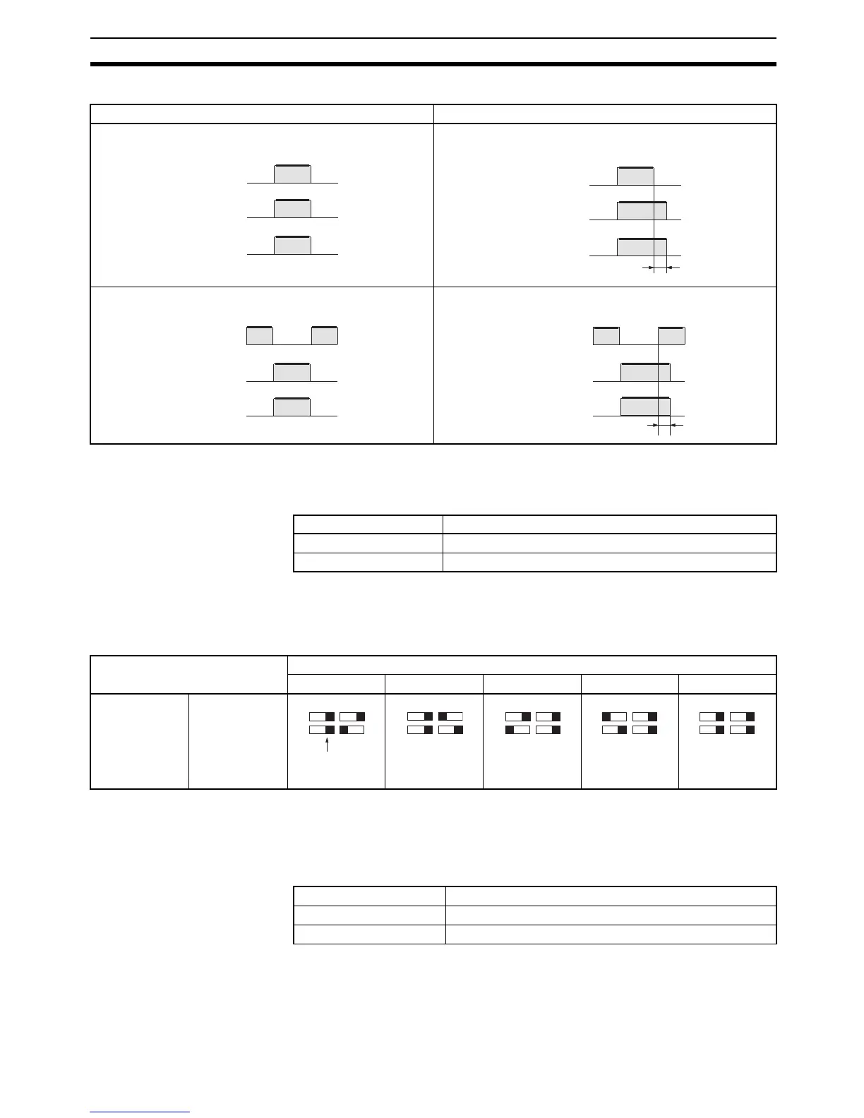
Timing Charts
Note The operation mode selector and timer selector must be set before mounting
the E3X-MA11 to the Sensor Unit.
Mode Selector
2-2-2 E2C-MA11 Proximity Sensor Module
Cable Length Switches Set the switches as shown below to the length of sensor cable being used
either for standard cable lengths or after cutting the cable.
Note 1. If two cables of the same length and diameter are being attached together
in parallel, position one of the cables 1 m above or below the other.
2. Set all switches to the right for the E2C-CR5B.
Timer Switch
Timer selector set to OFF (0ms) Timer selector set to ON (10 ms)
Operation indicator
(orange)
ON
OFF
Control output
ON
OFF
Light received
Light not received
Operation mode selector set to L • on (Light
ON)
10 ms
Operation mode selector set to L • on (Light
ON)
Operation indicator
(orange)
ON
OFF
Control output
ON
OFF
Light received
Light not received
Operation mode selector set to D
•
on (Dark
ON)
Operation indicator
(orange)
ON
OFF
Control output
ON
OFF
Light received
Light not received
Operation mode selector set to D
•
on (Dark
ON)
10 ms
Operation indicator
(orange)
ON
OFF
Control output
ON
OFF
Light received
Light not received
Setting Function
RUN Normal operation
SET Axis adjustment or sensitivity adjustment (teaching).
Sensor Cable length
0 to 1 m 1 to 2 m 2 to 3 m 3 to 4 m 4 to 5 m
E2C-CR8A
E2C-CR8B
E2C-X1A
E2C-C1A
E2C-X1R5A
Position of the
switches of the
Amplifier Unit