EasyManuals Logo

Omron CQM1 User Manual

Omron CQM1
312 pages
To Next Page IconTo Next Page
To Previous Page IconTo Previous Page
Page #163 background imageLoading...
Page #163 background image
144
Switch Settings Section 2-2
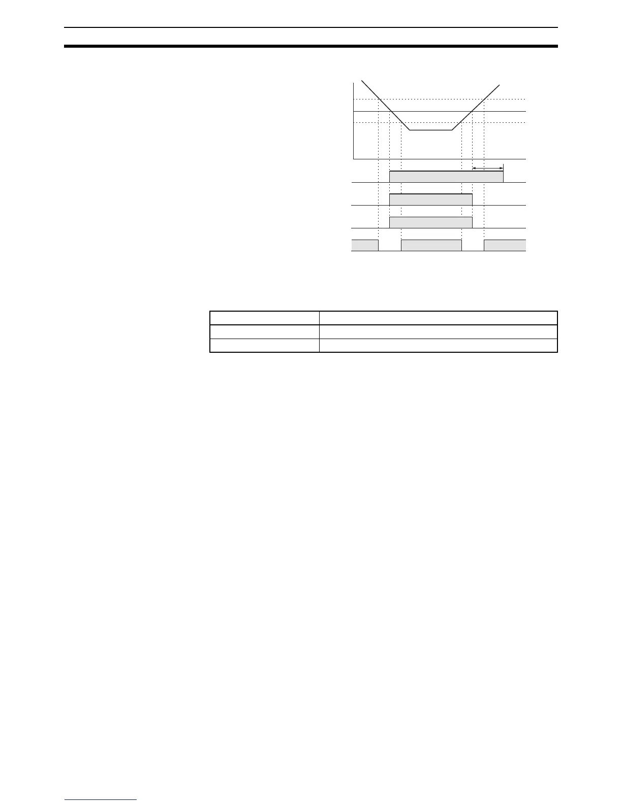
The following is an example of a sensor output operation chart.
Note Set the switches on the side panel before mounting the Module to the Sensor
Unit.
Mode Selector
Note 1. Refer to 3-4-1 E3X-MA11 Optical Fiber Photoelectric Module for the fiber
lock lever of the E3X-MA11.
2. Refer to SECTION 4 Sensor Module Operation for details on the operation
of the mode selector and teaching button.
10 ms
ON
OFF
ON
OFF
Sensing distance
Approx. 107%
Setting distance 100%
h
Control output (OFF-
delay activated)
Control output
(OFF-delay deactivated)
Operation indicator
(orange)
Stability operation
indicator (green)
Approx. 93%
ON
OFF
ON
OFF
Setting Function
RUN Normal operation
SET Sensitivity adjustment (teaching)

Table of Contents

Questions and Answers:

Question and Answer IconNeed help?

Do you have a question about the Omron CQM1 and is the answer not in the manual?

Omron CQM1 Specifications

General IconGeneral
ModelCQM1
I/O CapacityUp to 256 I/O points
Programming LanguageLadder Logic
Timer/Counter128 timers/counters
Operating Temperature0 to 55°C
Humidity10 to 90% RH (non-condensing)
Power Supply24 VDC or 100-240 VAC
Communication PortsRS-232C
Memory Capacity3.2K words
Instruction SetBasic and advanced instructions
MemoryRAM (battery-backed)
Program Memory3.2K words
Storage Temperature-20 to 75°C

Related product manuals