59
Appendix B
Troubleshooting
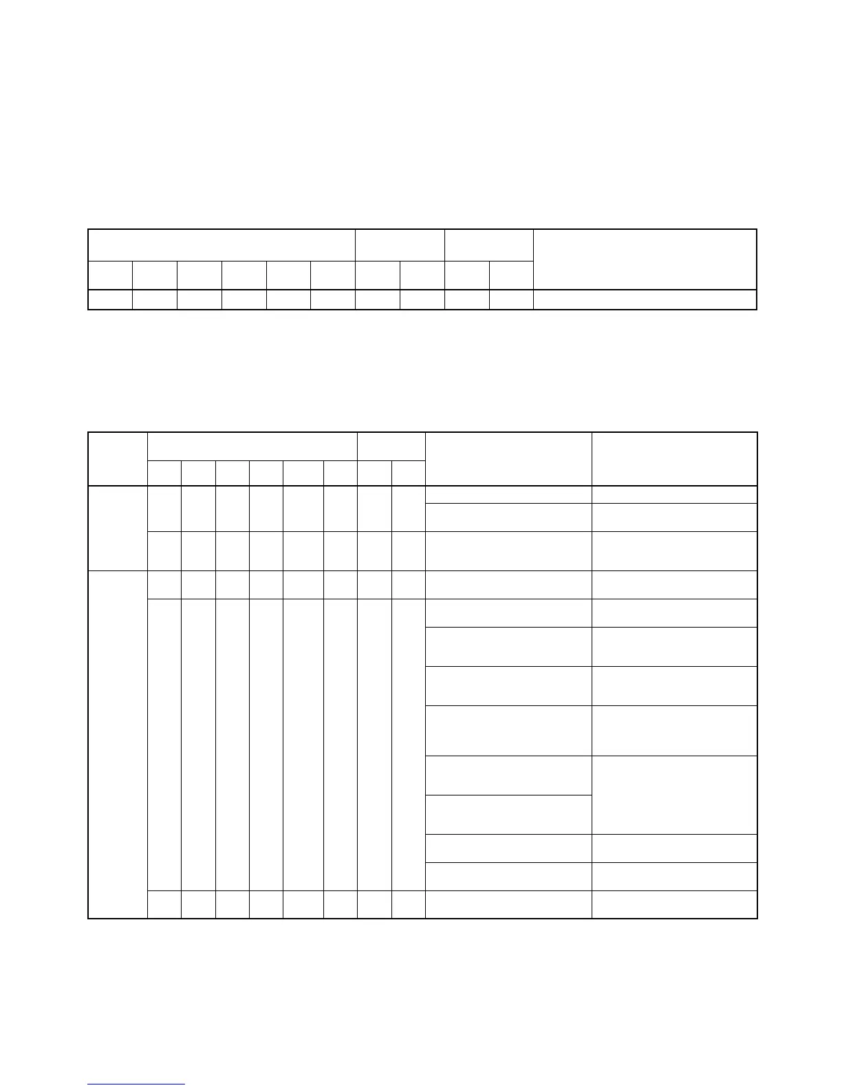
Indicator Status During Normal Operation
❍: Lit, ▲: Flashing, X: Not lit
Any other indicator display indicates an error. Refer to the table below.
Indicator Alarm Table
The table below shows the description and remedy of an error occurring in the G730 Interface Unit.
❍: Lit, ▲: Flashing, X: Not lit, “––”: Status not relevant.
Master Expansion
Master
Slave Comments
RDY T/R
RDY
T/R END NODE ALM RDY T/R PWR T/R
❍❍▲
XX X
❍▲❍▲
All T/R indicators flash.
Error Master Expansion
Master
Description Remedy
RDY T/R
RDY
T/R END NODE ALM RDY T/R
Errors
before or
after nor-
mal oper-
ation
X––––––
––
–
X –– Power not turned on. Turn the power on.
Units not completely connected.
End cover not attached.
Refer to unit manual and correct
set up.
–– X X X X X –– –– Abnormal Master. Turn power off and back on.
Replace Master if same error re-
occurs.
Errors
before
normal
operation
❍ X ▲❍❍X––❍❍Slave address set between #28
and #30.
Set Slave address between #0
and #27.
❍ X ▲❍
X
––
❍❍No terminator set. Set the Slave connected at the
end as the terminator.
Multiple terminators exists in a
system.
Only one terminator allowed per
system. Wire separate systems
with one Master each.
Different types of communica-
tions Master exist.
Do not mix Master (G7M21) with
different types of communica-
tions Master.
Transmission path shorted.
Transmission path discontinuity.
Transmission path + and –
wiring reversed.
Correctly wire the transmission
path.
Expansion Masters exist with
the same input/output type and
duplicate unit #.
Correct settings to give unique
unit # and Slave address.
Expansion Masters exist with
the same input/output type and
duplicate system address.
The Slave set as terminator is
not turned on.
Turn on the terminator Slave.
The terminator is set to Slave
address #31.
Set terminator Slave address
between #0 and #27.
❍ X ▲▲X––❍❍Multiple terminators set Set only the final Slave to termi-
nator.