94
Bit Number Allocation Section 3-2
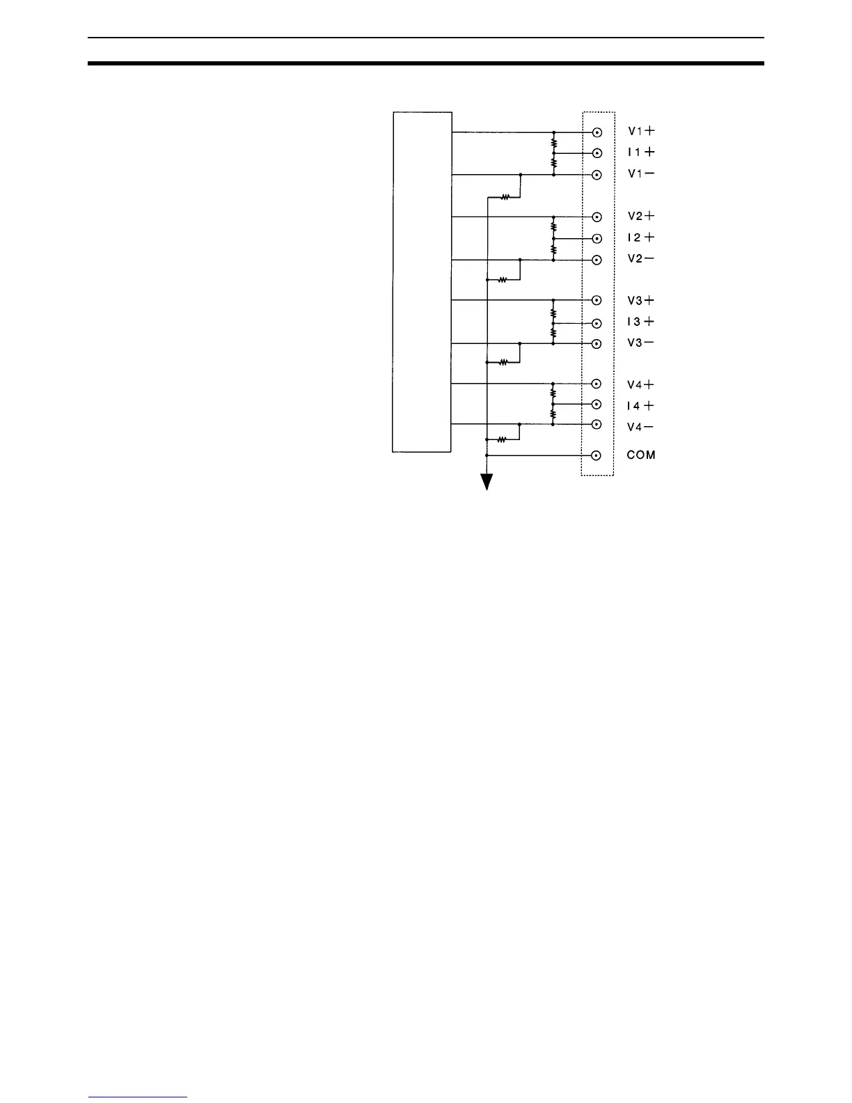
Following is the input circuit for the Analog Input Unit.
When the CQM1-IPS02 Analog Power Supply Unit is connected to the CQM1-
AD021 Analog Input Unit and CQM1-DA021 Analog Output Unit, each analog
ground is connected.
3-2 Bit Number Allocation
Two input words or four input words can be allocated to the Analog Input Unit,
which are specified with the DIP switch of the Analog Input Unit. Refer to
page 87, DIP Switch Function for details.
3-2-1 Word Allocation
Input words are allocated according to the mounting order (from left to right) of
the Units. Refer to the CQM1H Programming Manual (W364), 3-2-3 I/O Allo-
cation or the CQM1 Programming Manual (W228), 3-1 CQM1 Memory Area
Functions for details on I/O word allocation.
1 MΩ
250 Ω
10 kΩ
1 MΩ
250 Ω
10 kΩ
1 MΩ
250 Ω
10 kΩ
1 MΩ
250 Ω
10 kΩ
Analog ground
Internal circuit