95
Bit Number Allocation Section 3-2
No word is allocated to the Analog Power Supply Unit. Mount the Analog
Power Supply Unit next to the Analog Input Unit either to the left or right.
3-2-2 Bit Allocation
The following shows how the words allocated to the Analog Input Unit are
used. Any conversion data is stored in hexadecimal.
Error Flag (Bit 13 of the First Word)
Bit 13 of the first word functions as an error flag. The error flag turns ON
(becomes 1) if an invalid setting is made with the DIP switch (e.g., prohibiting
the conversion of all words) and the Analog Input Unit does not operate. If the
input range of input 1 is –10 to 10 V and the conversion data of input 1 is neg-
ative, however, this bit turns ON because 2’s complement is used to indicate
the negative data. If bit 15 of the first word is OFF and bit 13 is ON, it indicates
an error.
Broken Wire Detection Flag (Bit 12 of Each Word)
If the input range of the Analog Input Unit is 1 to 5 V or 4 to 20 mA and the
voltage of an input is less than approximately 0.95 V or the current of an input
is less than approximately 3.8 mA, the broken wire detecting function of the
Analog Input Unit will be activated and the bit 12 of the corresponding word
will turn ON (the bit will become 1).
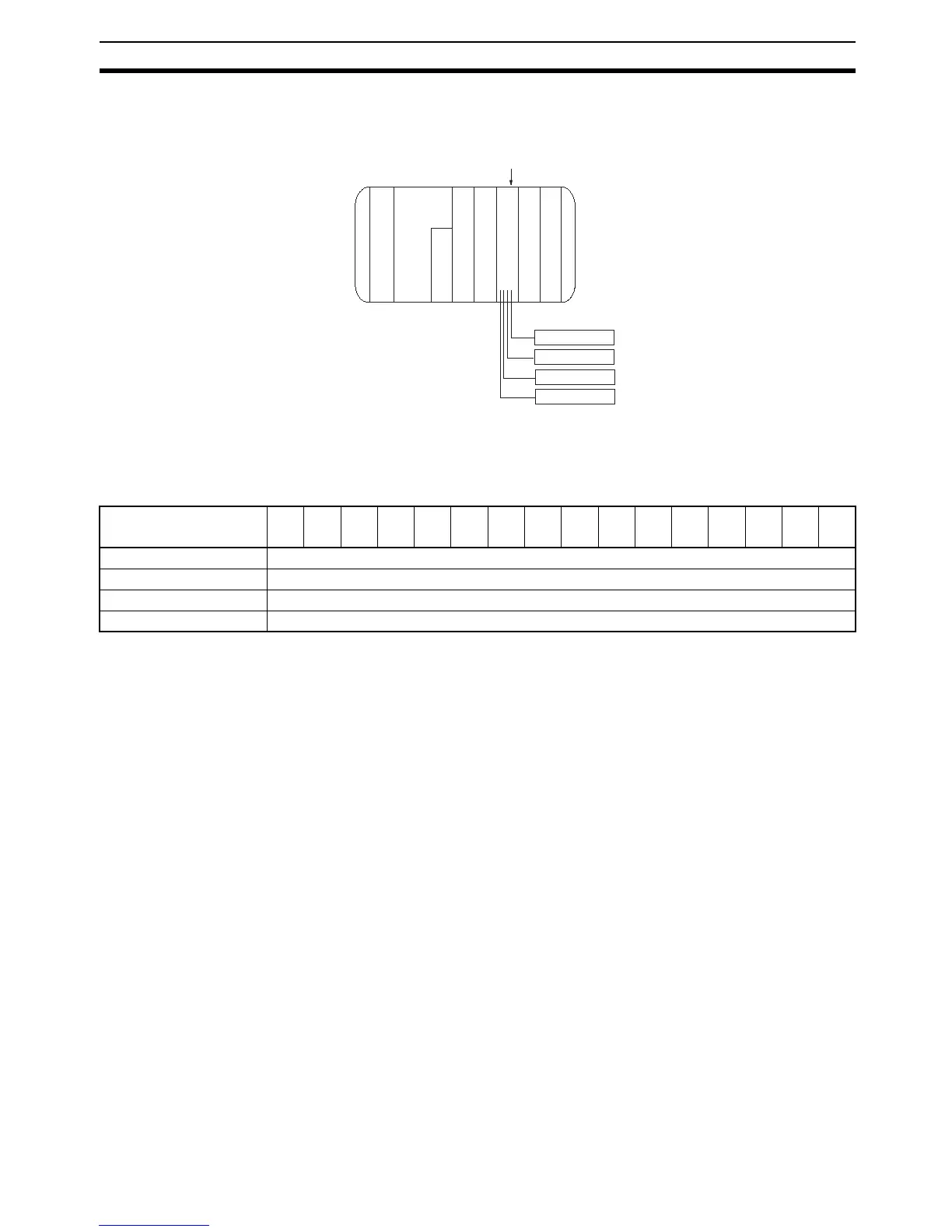
Example: Four words are occupied.
Words 002 to 005 are used.
Word
CPU
000
001
006
100
IN 16 points
Sensor
Sensor
Sensor
Sensor
(Input 1)
(Input 2)
(Input 3)
(Input 4)
CQM1H/CQM1
IN 16 points
IN 16 points
Out 16 points
P
S
A
D
I
P
S
PS : Power Supply Unit
CPU : CPU
IN : Input Unit and terminals
OUT : Output Unit
IPS : Analog Power Supply Unit
AD : Analog Input Unit
Bit
Word
15 14 13 12 11 10 09 08 07 06 05 04 03 02 01 00
n Input 1 conversion data
n + 1 Input 2 conversion data
n + 2 Input 3 conversion data
n + 3 Input 4 conversion data