EasyManuals Logo

Omron CQM1 User Manual

Omron CQM1
312 pages
To Next Page IconTo Next Page
To Previous Page IconTo Previous Page
Page #267 background imageLoading...
Page #267 background image
248
Nomenclature Section 2-3
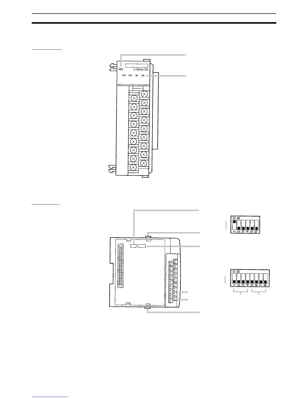
2-3 Nomenclature
Front View
Side View
Ready indicator (green, lit when the Unit is
recognized as the Temperature Control Unit)
Four-loop Models
OUT1 to OUT4 indicators (orange, lit when
control output is ON)
Two-loop Models
OUT1 and OUT2 indicators (orange, lit when
control output is ON)
HB1 and HB2 indicators (red, lit when a
heater burnout has been detected)
Terminal screws: M3
Function DIP switch (SW1)
Cover
Loops
1 and 3
Slide lock
Te rm in al s
Slide lock
Input type DIP switch (SW2)
ON
OFF
ON
OFF
Loops
2 and 4

Table of Contents

Questions and Answers:

Question and Answer IconNeed help?

Do you have a question about the Omron CQM1 and is the answer not in the manual?

Omron CQM1 Specifications

General IconGeneral
ModelCQM1
I/O CapacityUp to 256 I/O points
Programming LanguageLadder Logic
Timer/Counter128 timers/counters
Operating Temperature0 to 55°C
Humidity10 to 90% RH (non-condensing)
Power Supply24 VDC or 100-240 VAC
Communication PortsRS-232C
Memory Capacity3.2K words
Instruction SetBasic and advanced instructions
MemoryRAM (battery-backed)
Program Memory3.2K words
Storage Temperature-20 to 75°C

Related product manuals