141
Nomenclature Section 2-1
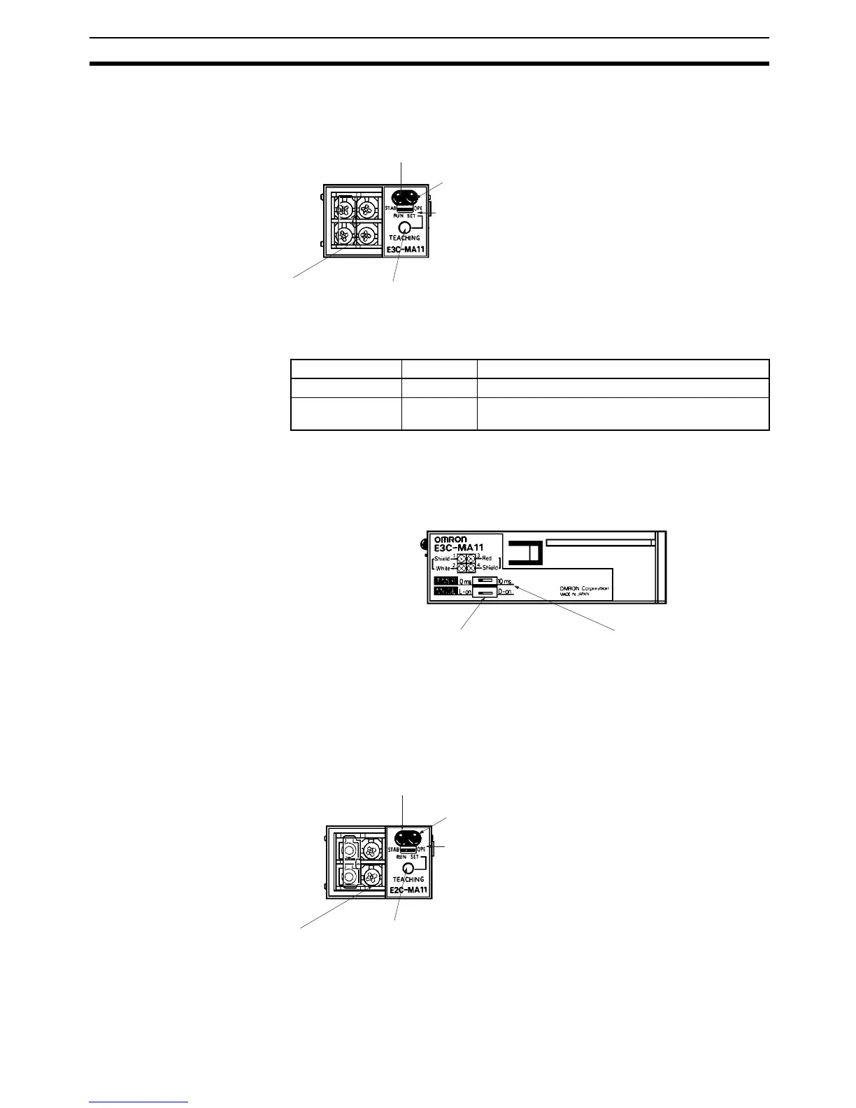
2-1-4 Photoelectric Module
Indicators
Note When the mode selector is set to SET, the operation indicator and stability
operation indicator are used to monitor teaching. Refer to 2-2 Switch Settings
for details.
2-1-5 Proximity Sensor Module
Teaching button
Mode selector (SET for teaching and RUN for normal operation.)
Operation indicator
(orange)
Stability operation indicator (green)
Front View
E3C-MA11
Sensor code connection terminals
(Refer to 2-2 Switch Settings for details.)
(Refer to 3-4-2 E3C-MA11 Photoelectric Module for
details.)
Name Color Function
OPE Orange Lit when the control output is ON.
STAB Green Lit during stable light ON or dark ON, which can be
selected with the operation mode selector.
Operation mode selector
L • on: Light ON
D • on: Dark ON
Timer selector
0 ms: No timer
10 ms: OFF-delay timer
Side View
(Refer to 2-2 Switch
Settings for details.)
(Refer to 2-2 Switch
Settings for details.)
Sensor code connection terminals
Teaching button
Mode selector (SET for teaching and RUN for normal operation)
Operation indicator
(orange)
Stability operation indicator (green)
Front View
E2C-MA11
(Refer to 3-4-3 E2C-MA11 Proximity Sensor Module for
details.)
(Refer to 2-2-2 E2C-MA11 Proximity Sensor Module for
details.)