82
Featu res Section 1-1
1-1 Features
1-1-1 Analog Input Unit
• The CQM1-AD041 is a SYSMAC CQM1H/CQM1-series Analog Input Unit
that converts analog signals into digital signals.
• A single Analog Input Unit converts 4-point analog input into 12-bit digital
output. It is possible to reduce the number of input words that the Analog
Input Unit occupies by limiting the number of the Analog Input Unit’s input
points to a maximum of two. Refer to page 87 DIP Switch Functions for
details.
• Converted data is stored in the input word allocated to the Analog Input
Unit. The converted data is used by just reading the contents of the input
word. Refer to 3-2-1 Word Allocation for details.
• The Analog Input Unit has input signal voltage ranges of –10 to 10 V, 0 to
10 V, and 1 to 5V, any of which can be combined freely with the CQM1-
AD041’s input signal current range of 4 to 20 mA.
• The Analog Input Unit incorporates a mean value processing function so
that it outputs stable conversion data.
• The Analog Input Unit incorporates a broken wire detecting function, with
which the Analog Input Unit detects the disconnection of any input wire
that has been connected to the Analog Input Unit given the input range is
4 to 20 mA or 1 to 5 V.
1-1-2 Analog Power Supply Units
• The CQM1-IPS01 and CQM1-IPS02 are Analog Power Supply Units for
the Analog Input Unit.
• The CQM1-IPS01 connects to a single Analog Input Unit.
• The CQM1-IPS02 connects to a maximum of two Analog Input Units.
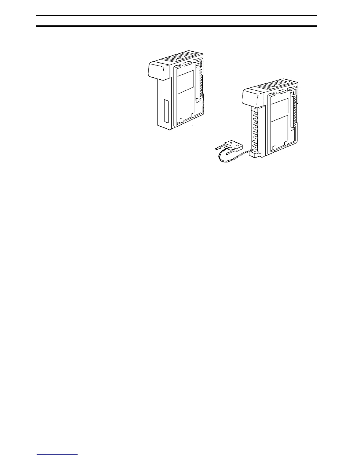
Analog Input Unit
Analog Power Supply Unit