255
Application Section 2-6
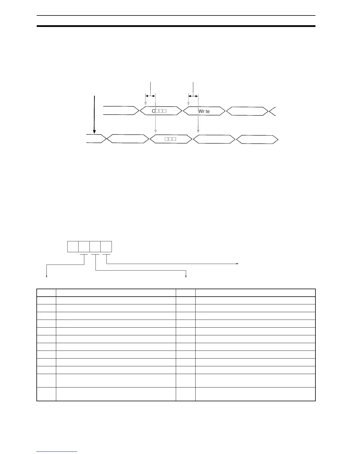
2-6-1 Communications Procedure
The following diagram illustrates the procedures used to set parameters, mon-
itor data, and read data.
Note No commands are set at startup.
1,2,3... 1. Output word: An I/O allocation command (C@@@) is set to specify the loop
and the items to be set and monitored.
2. Input word: The I/O allocation command set in the output word will be set
by the system as a “Command Acknowledged Flag” to indicate that the
command has been acknowledged.
3. Output word: The write data for the I/O allocation command set in 1. is set.
4. Input word: After the data specified in 3. has been set, the data specified
to be monitored in 1. will be set by the system. This also functions as a
“Write Completed Flag” to indicate that the write operation has been com-
pleted.
Output
word
Input
word
Power ON
Initialization
Read data
Initialization
completed
FFFF
0000
C
(((
C
(((
Write data
60 ms max. 60 ms max.
(1) (2) (3) (4)
Value Item to be set Value Item to be monitored
0 Set point 0 Set point
1 Proportional band (for advanced PID) 1 Proportional band (for advanced PID)
2 Integral time (for advanced PID) 2 Integral time (for advanced PID)
3 Derivative time (for advanced PID) 3 Derivative time (for advanced PID)
4 Hysteresis (for ON/OFF control) 4 Hysteresis (for ON/OFF control)
5 Control cycle (for advanced PID or manual control) 5 Control cycle (for advanced PID or manual control)
6 Input shift value 6 Input shift value
7 No item set (See note 2.) 7 Process value
8 Manual manipulated variable 8 Manipulated variable
9 Do not set. 9 Status
A Heater burnout alarm setting (only for models with
heater burnout alarms)
A Heater burnout alarm setting (only for models with
heater burnout alarms)
B Do not set. B Heater current (only for models with heater burnout
alarms)
C
Item To Be Set Item To Be Monitored
Output word
Loop number: 1 to 4