136
System Construction Section 1-4
The following sensors can be used with the E3C-MA11 Photoelectric Module.
The following sensors can be used with the E2C-MA11 Proximity Sensor
Module.
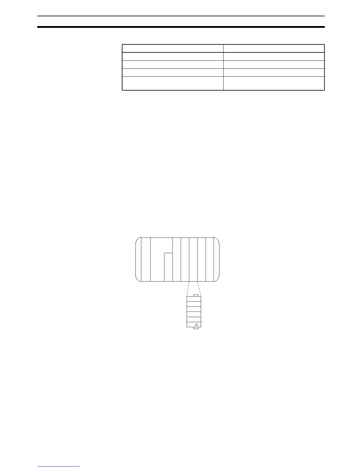
1-4 System Construction
The CQM1H/CQM1 treats the CQM1-SEN01 as a four-point Input Unit. Inputs
are allocated from word 000 including the built-in input bits of the CPU of the
CQM1H/CQM1.
The following is an example of word allocation. The CQM1-SEN01 occupies
one input word. Any bits without a sensor module cannot be used as work
bits. Any bits connected to a dummy module is always OFF.
Example
Note Refer to 3-2-3 I/O Allocation of the CQM1H Programming Manual or 3-2 Allo-
cating I/O Bits of the CQM1 Programming Manual for details on I/O word allo-
cation.
Sensing method Model
Thru-beam E3C-S10, E3C-1, and E3C-2
Diffuse reflective E3C-DS5W, E3C-DS10
Convergent reflective E3C-LS3R
Mark detection reflective E3C-VS1G, E3C-VS3R, E3C-VM35R,
and E3C-VS7R
• E2C-CR5B
• E2C-CR8A
• E2C-CR8B
• E2C-X1A
• E2C-C1A
• E2C-X1R5A
Word
CPU
000
001
100
101
IN 16 points
CQM1H/CQM1
IN 16 points
Out 16 points
P
S
PS : Power Supply Unit
CPU : CPU
IN : Input Unit and terminals
OUT : Output Unit
SEN : Sensor Unit
IN 16 points
Out 16 points
SEN 4 points
002
003
Slot no. Bit
0
1
2
3
00300
00301
00302
00303