140
Nomenclature Section 2-1
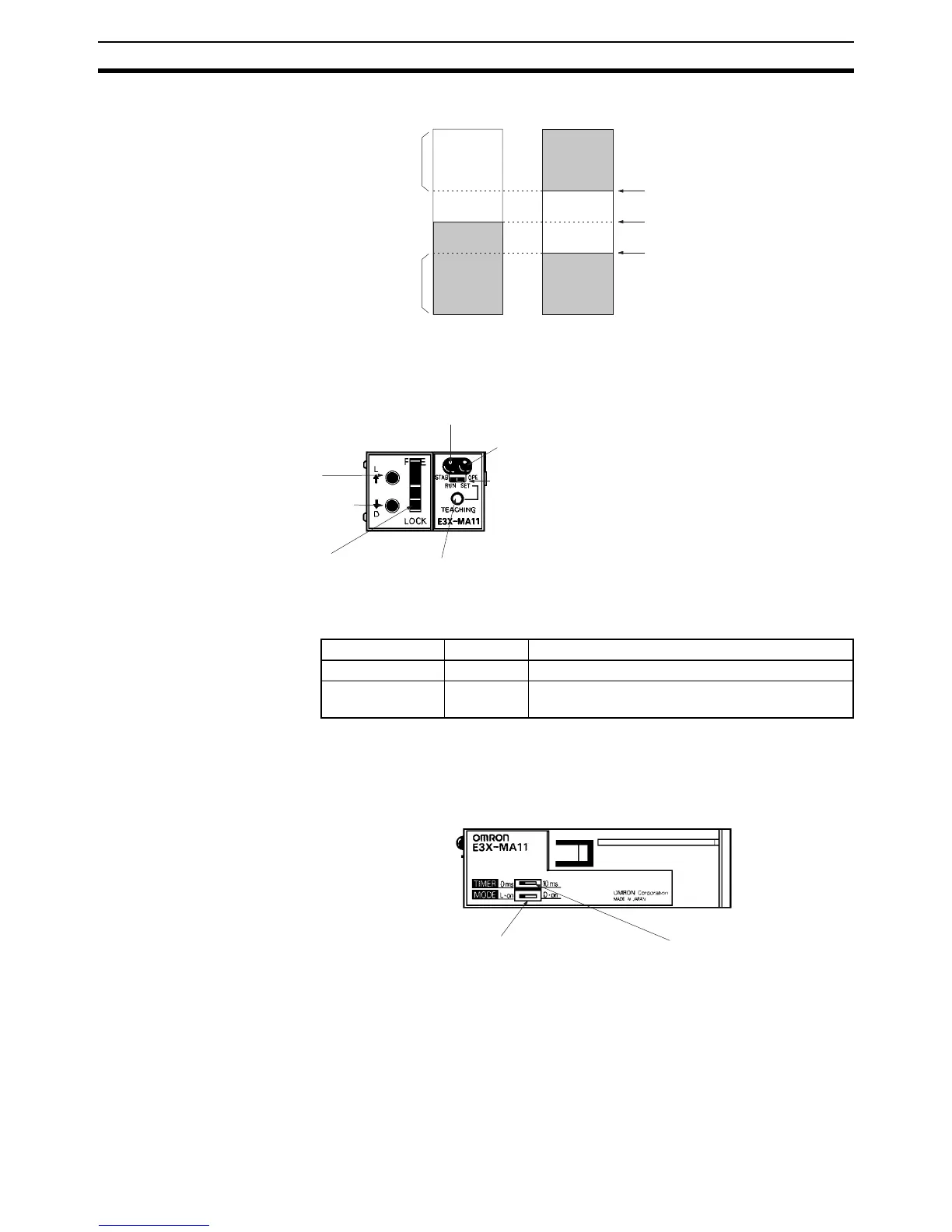
2-1-3 Optical Fiber Photoelectric Module
Indicators
Note When the mode selector is set to SET, the operation indicator and stability
operation indicator are used to monitor teaching. Refer to 2-2 Switch Settings
for details.
Operation indica-
tor (orange)
Stability operation
indicator
Stable non-
sensing zone
Stable sens-
ing zone
OFF
ON
Setting distance
x approx. 1.07
Setting distance
Setting distance
x approx. 0.93
ON
OFF
ON
Fiber insertion mouth (light emitting terminal)
Fiber insertion mouth (light reception terminal)
Fiber lock lever
FREE: Fiber is released.
LOCK: Fiber is locked.
Teaching button
Mode selector (SET for teaching and RUN for normal operation.)
Operation indicator
(orange)
Stability operation indicator (green)
Front View
E3X-MA11
(Refer to 3-4-1 E3X-MA11 Optical Fiber
Photoelectric Module for details.)
(Refer to 3-4-1 E3X-MA11 Optical Fiber
Photoelectric Module for details.)
(Refer to 2-2 Switch Settings for details.)
Name Color Function
OPE Orange Lit when the control output is ON.
STAB Green Lit during stable light ON or dark ON, which can be
selected with the operation mode selector.
Operation mode selector
L • on: Light ON
D • on: Dark ON
Timer selector
0 ms: No timer
10 ms: OFF-delay timer
Side View
(Refer to 2-2 Switch
Settings for details.)
(Refer to 2-2 Switch
Settings for details.)