5
System Configuration Section 1-2
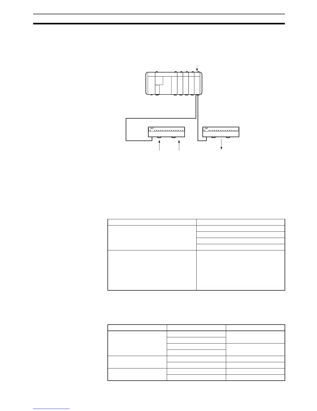
1-2 System Configuration
The following is a CQM1H/CQM1 system configuration with a B7A Interface
Unit.
Note The maximum transmission distance depends on the transmission delay time
and the power supply wiring.
Refer to 3-1 Connections to B7A Link Terminals.
1-3 Connecting Devices
1-3-1 CPU
The B7A Interface Unit connects to the following CPUs.
1-3-2 B7A Link Terminal
The B7A Interface Unit connects to the following 16-point B7A Link Terminals
with a standard I/O delay of 19.2 ms (typical).
Input
CQM1H/CQM1
B7A Interface Unit
Transmission distance: 500 m max.
B7A Link Terminal (for input) B7A Link Terminal (for output)
Switch Sensor Lamps
Name Model
CQM1H-series CPU CQM1H-CPU11
CQM1H-CPU21
CQM1H-CPU51
CQM1H-CPU61
CQM1-series CPU CQM1-CPU11-E
CQM1-CPU21-E
CQM1-CPU41-EV1
CQM1-CPU42-EV1
CQM1-CPU43-EV1
CQM1-CPU44-EV1
Name Model Transmission delay time
Screw terminal models B7A-T6@1 STANDARD (19.2 ms)
B7AS-T6@1
B7A-T6@6 RAPID (3 ms)
B7AS-T6@6
Module models B7A-T6D2 STANDARD (19.2 ms)
B7A-T6D7 RAPID (3 ms)
PC connector models B7A-T@E3 STANDARD (19.2 ms)
B7A-T@E8 RAPID (3 ms)