86
Nomenclature Section 2-1
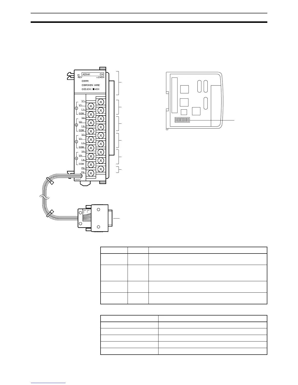
2-1 Nomenclature
2-1-1 Analog Input Unit
Indicators
Terminals
Indicators
Input terminal 1
Input terminal 2
Input terminal 3
Input terminal 4
Protective
ground terminal
Power supply
cable
DIP switch
Left View
Front View
CQM1-AD041
Terminal screws: M3
Name Color Function
RDY Green Lit while the CQM1H/CQM1 is turned on and the Analog
Input Unit is operating normally.
ERR Red Lit when pins 1 to 8 of the DIP switch on the left side of the
Analog Input Unit are all set to OFF (i.e., when the conver-
sion of all inputs is prohibited).
BROKEN
WIRE
Red Lit when an broken input wire is detected in an input range
of 4 to 20 mA at 1 to 5 V.
2CH/4CH Orange Lit when there are four words occupied. Not lit when there
are two words occupied.
Terminal Usage
Input terminal 1 Connect analog input for input 1.
Input terminal 2 Connect analog input for input 2.
Input terminal 3 Connect analog input for input 3.
Input terminal 4 Connect analog input for input 4.
Protective ground terminal Connect the shielded wire of the analog input cable.