8
Bit Allocation Section 1-5
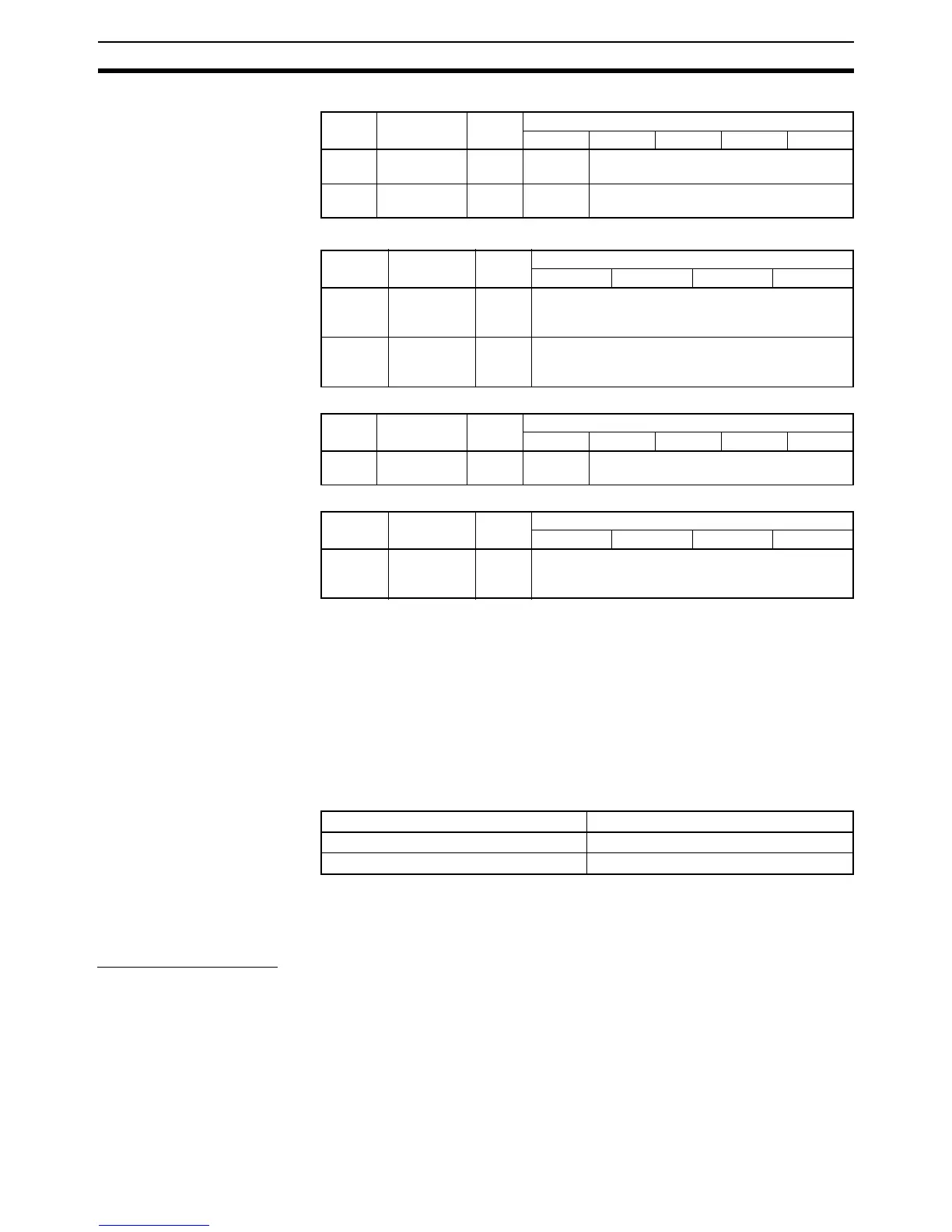
CQM-B7A13
CQM1-B7A03
CQM1-B7A12
CQM1-B7A02
Note 1. Bit 15 of the input address is allocated as follows, according to the DIP
switch input mode setting.
15-point input + 1 error mode setting = transmission error bit
16-point input = input bit 15
Refer to 2-2 Switch Settings.
2. Start word address (n: input, m: output)
3. See the following caution.
!Caution The minimum input time (minimum required time to read input signal from
CPU) at output bit of the B7A Interface Unit is as follows:
When a user program is created, make sure the ON/OFF signal range from
the CPU to the B7A Interface Unit’s output bit is larger than the above values.
If smaller than the above values, data might not be correct transmitted.
Transmission Errors
Power On If the input mode is set to 15IN+ERR, the transmission error bit becomes OFF
when the CQM1H/CQM1 power is turned on.
The transmission error bit turns ON if normal transmission with the input B7A
Link Terminal is not established within 10 ms.
All input bits remain OFF from the time CQM1H/CQM1 is turned on until nor-
mal transmission is established.
I/O Word no. Termi-
nal
Bit
15 14 to 12 11 to 8 7 to 4 3 to 0
Input n 1 See
note 1
Input bits
Input n + 1 2 See
note 1
Input bits
I/O Word no. Termi-
nal
Bit
15 to 12 11 to 8 7 to 4 3 to 0
Output
(see
note 3)
m 1 Output bits
Output
(see
note 3)
m + 1 2 Output bits
I/O Word no. Termi-
nal
Bit
15 14 to 12 11 to 8 7 to 4 3 to 0
Input n 1 See note
1
Input bits
I/O Word no. Termi-
nal
Bit
15 to 12 11 to 8 7 to 4 3 to 0
Output
(see
note 3)
m 1 Output bits
Transmission delay time Minimum input time
STANDARD (19.2 ms) 16 ms
RAPID (3 ms) 2.4 ms