53
Word Allocation Section 4-1
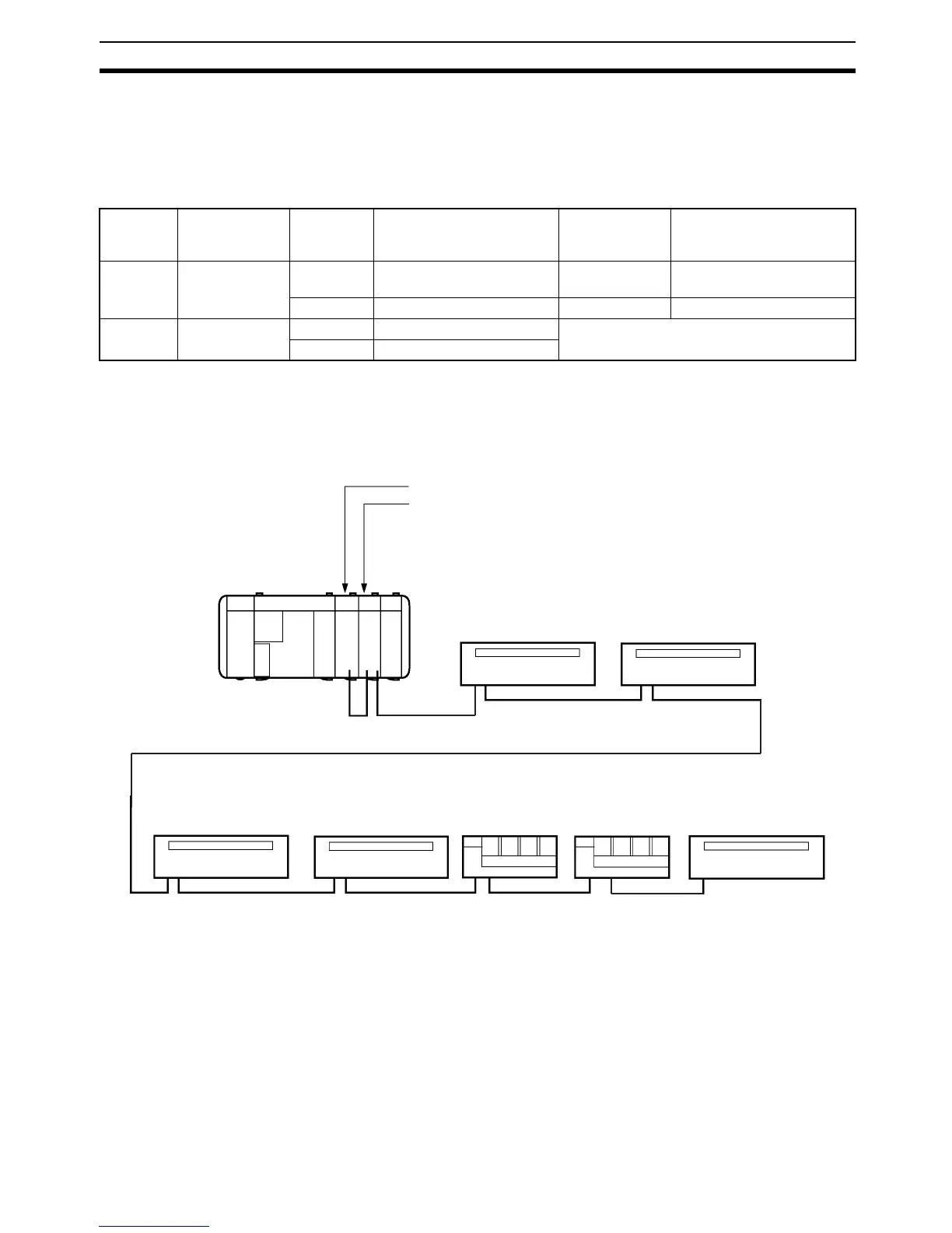
4-1-4 Word Allocation Example
In this example, the Master and output Expansion Master Unit 1 are set to 2
words and the Slaves comprise five 16-point Units and two 4-point Units. The
Slave I/O bit addresses corresponding to Unit I/O words and Slave address
allocations are shown in the table below.
In the following example, the Slaves are connected in order of ascending
Slave address. However, the connection order is independent of the Slave
address. The only requirement is that they are connected in series.
Set the Slave connected at the end as the terminator, regardless of its Slave
address.
I/O type CPU internal
input word
Master
word
Slave address Expansion
Master Unit 1
word
Slave address
Output --- 100 #0 (16-point output model) 102 #16, #17 (two 4-point Out-
put Units)
101 #4 (16-point output model) 103 #20 (16-point Output Unit)
Input 000 001 #8 (16-point input model) ---
002 #12 (16-point input model)
Master (I/O set to 2 words)
Expansion Master Unit 1
(output set to 2 words)
#0
Word 100
16-point
output
Bit address (OUT)
10000 to 10015
RS-485 total length 200 m
Set as terminator
#4
Word 101
16-point
output
Bit address (OUT)
10100 to 10115
#8
Word 001
16-point
input
#12
Word 002
16-point
input
#16
Word 102
4-point
output
#17
Word 102
4-point
output
#20
Word 103
16-point
output
Bit address (IN)
00100 to 00115
Bit address (IN)
00200 to 00215
Bit address (OUT)
10200 to 10203
Bit address (OUT)
10204 to 10207
Bit address (OUT)
10300 to 10315
CQM1H/CQM1