5-11
5-6 Setting the Frequency Reference
5-6-1 Selecting the Frequency Reference
The following description provides information on how to set the frequency reference in
the Inverter. Select the method according to the operation mode.
Remote mode: Select and set one out of ten frequency references in n004.
Local mode: Select and set one out of two frequency references in n008.
H Selecting the Frequency Reference (n004) in Remote Mode
• Select the input method of frequency references in remote mode.
• Five frequency references are available in remote mode. Select one of them according to the applica-
tion.
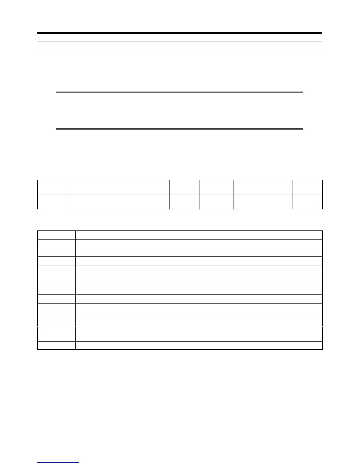
n004
Frequency Reference Selection Register 0104 Hex Changes during
operation
No
Setting
range
0 to 9 Unit of
setting
1 Default setting 0
Set Values
Value Description
0 The settings of the FREQUENCY adjuster in the Digital Operator are enabled. (See note 1.)
1 Frequency reference 1 (n024) is enabled.
2 The frequency reference control terminal (for 0- to 10-V input) is enabled. (See note 2.)
3 The frequency reference control terminal (for 4- to 20-mA current input) is enabled. (See note
3.)
4 The frequency reference control terminal (for 0- to 20-mA current input) is enabled. (See note
3.)
5 The pulse train command control input is enabled.
6 Frequency reference (0002 Hex) through RS-422/485 communications is enabled.
7 Multi-function analog voltage input (0 to 10 V) is enabled. This setting is not required unless
two analog inputs are required in PID control.
8 Multi-function analog current input (4 to 20 mA) is enabled. This setting is not required unless
two analog inputs are required in PID control.
9 Frequency reference input from option (DeviceNet Communications Unit) is enabled.
Note 1. The maximum frequency (FMAX) is set when the FREQ adjuster is set to MAX.
Note 2. The maximum frequency (FMAX) is set with 10 V input.
Note 3. The maximum frequency (FMAX) is set with 20 mA input, provided that SW2 on the control
PCB is switched from V to I.
Basic Operation
Chapter 5

 Loading...


