7-8
7-2 Message Communications Basic Format
The following description provides information on the format of message data (DSR and
response data).
Message communications of the Inverter conform to the MODBUS Communications
Protocol, which does not require message start and end processing.
(The MODBUS Communications Protocol is a trademark of AEG Schneider Automa-
tion.)
H Communications Format
• The following format is used for message data communications.
• Message data consists of a Slave address, function code, communications data, and error check
block.
Message data (DSR message
and response)
Slave address
1 byte
Function code
1 byte
Communications
data
Error check
block
2 bytes
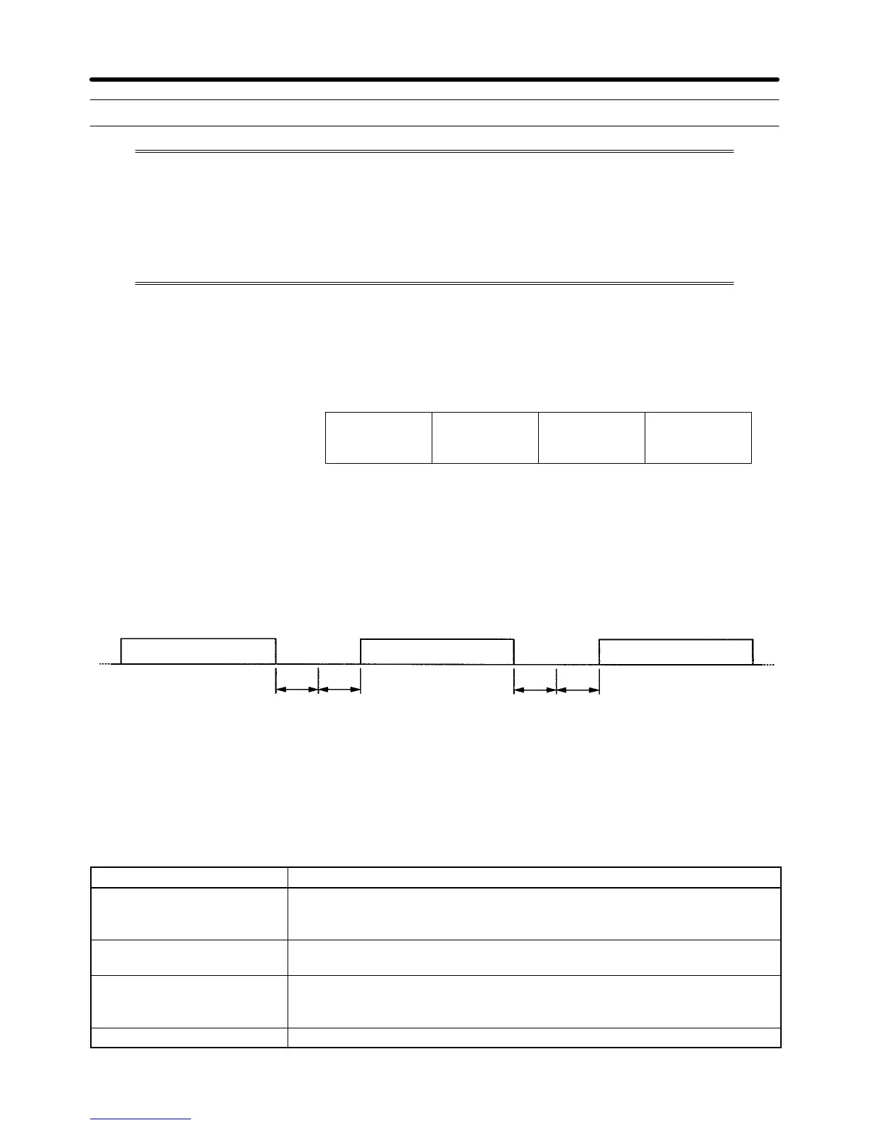
H Message Interval
• When the Inverter receives a DSR message from the Master, the Inverter waits for a period that is
equivalent to 24 bits in length and a Send Wait Time set in n156. Then the Inverter will return a
response. Set n156 according to the Master’s processing time or the timing adjustment.
• When the Master issues the next message after receiving the response from the Inverter, the Master
must wait for a 24-bit period plus another period of at least 10 ms.
DSR message from Master
Response from Inverter
DSR message from Master
24-bit (or 3-byte)
standby period
Standby period
set in n156
24-bit (3-byte)
standby period
Set a standby period of
10 ms or more for the
Master.
H Message Data Configuration
• The communications message is configured entirely of hexadecimal data. (ASCII and FINS are not
used.)
• Communications data is divided into the four areas shown in the following table.
Data name Description
Slave address Set the Slave address (the set value in n153) of the Inverter, to which the
DSR message is sent. The Slave address must be within a range from 00 to
32 (00 to 20 Hex).
Function code A command giving instructions of the details of processing to the Inverter.
Example: Data read (03 Hex) and data write (10 Hex)
Communications data Data attached to the command.
Example: The register number of read start data and the number of registers
of read data
Error check CRC-16 check code for checking the reliability of the message data.
Communications Chapter 7

 Loading...


