5-12
Note 4. Set n149 for the pulse train input scale to the pulse train frequency that is equivalent to the
maximum frequency (FMAX).
• The frequency reference set in n004 functions as frequency reference 1 when the Inverter is in multi-
step speed operation. The set values in n025 through n031 and n120 through n127 for frequency ref-
erences 2 through 16 are enabled.
H Selecting the Frequency Reference (n008) in Local Mode
• Select the input method of frequency references in local mode.
• Two frequency references are available in local mode. Select one of them according to the application.
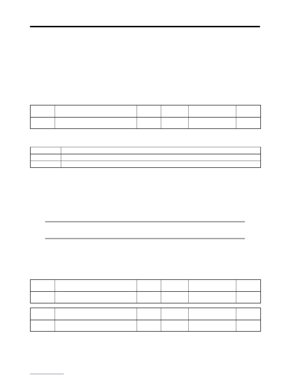
n008
Frequency Reference Selection in
Local Mode
Register 0108 Hex Changes during
operation
No
Setting
range
0, 1 Unit of
setting
1 Default setting 0
Set Values
Value Description
0 The settings of the FREQ adjuster in the Digital Operator are enabled. (See note 1.)
1 Key sequences on the Digital Operator are enabled. (See note 2.)
Note 1. The maximum frequency (FMAX) is set when the FREQ adjuster is set to MAX.
Note 2. The frequency reference can be set with key sequences while the FREF indicator is lit or with
the set value in n024 for frequency reference 1. In either case, the value is set in n024.
5-6-2 Upper and Lower Frequency Reference Limits
Regardless of the methods of operation mode and frequency reference input, the upper
and lower frequency reference limits can be set.
H Setting the Upper and Lower Frequency Reference Limits (n033 and
n034)
• Set the upper and lower frequency reference limits as percentage based on the maximum frequency
as 100%.
n033
Upper Frequency Reference Limit Register 0121 Hex Changes during
operation
No
Setting
range
0% to 110%
(Max. frequency = 100%)
Unit of
setting
1% Default setting 100
n034
Lower Frequency Reference Limit Register 0122 Hex Changes during
operation
No
Setting
range
0% to 110%
(Max. frequency = 100%)
Unit of
setting
1% Default setting 0
Note If n034 is set to a value less than the minimum output frequency (FMIN), the Inverter will have no
output when a frequency reference less than the minimum output frequency input is ON.
Basic Operation
Chapter 5
 Loading...


