EasyManuals Logo

Omron SYSDRIVE 3G3MV SERIES User Manual

Omron SYSDRIVE 3G3MV SERIES
344 pages
To Next Page IconTo Next Page
To Previous Page IconTo Previous Page
Page #44 background imageLoading...
Page #44 background image
2-12
2-2-1 Terminal Block
To wire the terminal block of the Inverter, remove the front cover, terminal cover (unless
the Inverter is a low-capacity 200-V model), and bottom cover from the Inverter.
There is a label under the front cover indicating the arrangement of main circuit termi-
nals. Be sure to remove the label after wiring the terminals. The output terminal of the
motor has a label as well. Remove the label before wiring the motor terminal.
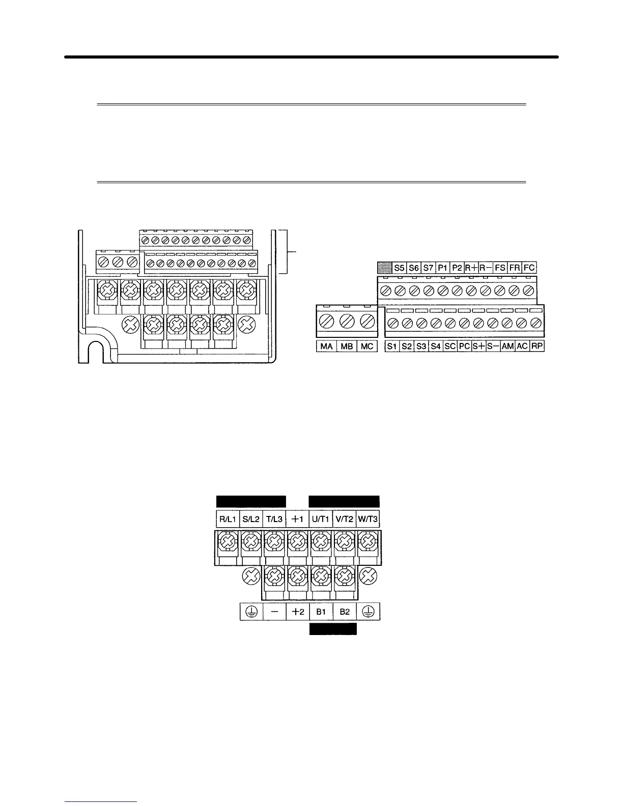
H Arrangement of Control Circuit Terminals
Control circuit terminals
H Arrangement of Main Circuit Terminals
D 3G3MV-A2001 through 3G3MV-A2007 (0.1 through 0.75 kW):
3-phase 200-V AC Input
3G3MV-AB001 through 3G3MV-AB004 (0.1 through 0.4 kW):
Single-phase 200-V AC Input
Power supply input
Motor output
Braking Resistor
Note For single-phase input, connect R/L1 and S/L2.
Design Chapter 2

Table of Contents

Questions and Answers:

Question and Answer IconNeed help?

Do you have a question about the Omron SYSDRIVE 3G3MV SERIES and is the answer not in the manual?

Omron SYSDRIVE 3G3MV SERIES Specifications

General IconGeneral
ModelSYSDRIVE 3G3MV SERIES
CategoryInverter
Input Frequency50/60 Hz
Output Frequency0.1 to 400 Hz
Cooling MethodForced Air Cooling
Input Voltage200 to 240 VAC, 380 to 480 VAC
Horsepower Range0.1 to 15 HP
Power Range0.1 to 11 kW
Overload Capacity150% for 60 seconds
Braking UnitBuilt-in
Protection FunctionsOvercurrent, Overvoltage, Undervoltage, Overheat
CommunicationRS-485
Ambient Temperature-10 to 50°C
Storage Temperature-20 to 65°C
Humidity5 to 95% RH (non-condensing)
Vibration5.9 m/s² or less
Voltage Class200V, 400V

Related product manuals