7-13
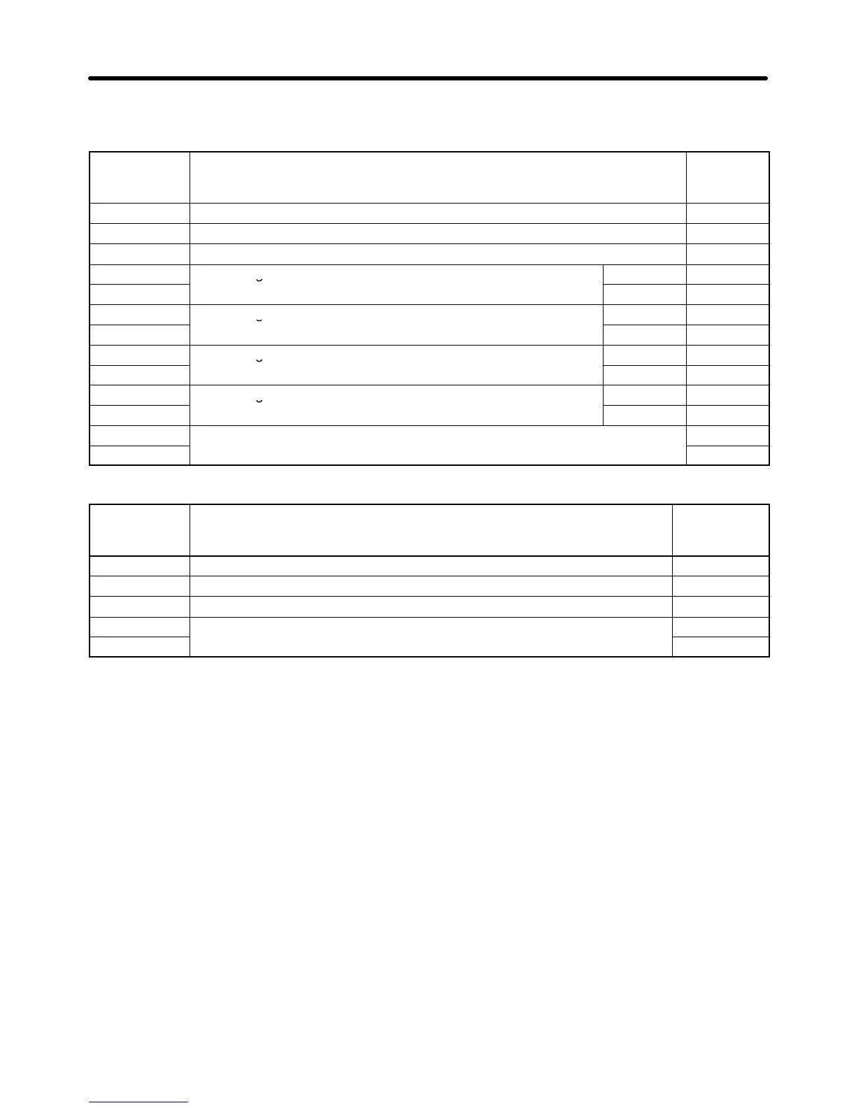
D Response
Normal
Byte No. Data Data
example
(Hex)
1 Slave address 02
2 Function code 03
3 Number of bytes of attached data 08
4
Data in register No. 0020
MS B 00
5
LSB 65
6
Data in register No. 0021
MSB 00
7
LSB 00
8
Data in register No. 0022
MSB 00
9
LSB 00
10
Data in register No. 0023
MSB 01
11
LSB F4
12
CRC-16 check
AF
13 82
Error
Byte No. Data Data
example
(Hex)
1 Slave address 02
2 Function code 83
3 Error code 03
4
CRC-16 check
F1
5 31
7-3-2 Data Write/Broadcast Data Write (Function Code: 10 Hex)
H Settings and Response
• To write data to the Inverter, such as control I/O and parameter set value data, issue the following DSR
message.
• Consecutive data of a maximum of 16 words (32 bytes for 16 registers) can be written per DSR mes-
sage.
• The register number is allocated to each function item, such as control I/O and parameter functions.
The register number of each parameter is indicated wherever the parameter is explained in this
manual and in Section 10 List of Parameters. For register numbers other than those of parameters,
refer to 7-6 Register Number Allocations in Details.
Note 1. A parameter corresponds to one register (one word), so the “number of registers of write data”
indicates the number of parameters to be written (i.e., the number of consecutive registers
beginning with the first register number).
Note 2. The “number of bytes of attached data” indicates the number of bytes of data written to the
registers attached from that point onwards. The number of registers must equal the number of
bytes divided by two.
Communications Chapter 7

 Loading...


