2-34
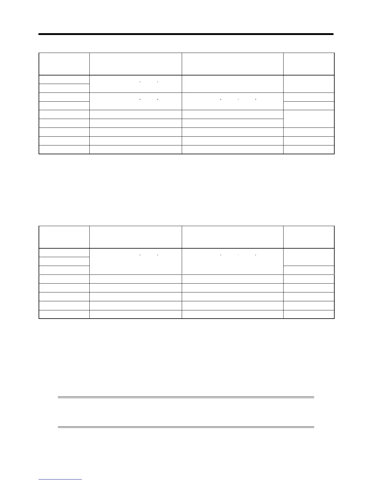
D Braking Resistors and Braking Resistor Units for 200-V-class Inverters
Inverter
3G3MV-
Braking Resistor
(3% usage rate ED)
3G3IV-
Braking Resistor Unit
(10% usage rate ED)
3G3IV-
Minimum
connection
resistance
A2001/AB001
PERF150WJ401 (400 Ω) --- 300 Ω
A2002/AB002
A2004/AB004
PERF150WJ201 (200 Ω) PLKEB20P7 (200 Ω, 70 W)
200 Ω
A2007/AB007
120 Ω
A2015/AB015 PERF150WJ101 (100 Ω) PLKEB21P5 (100 Ω, 260 W)
60 Ω
A2022/AB022 PERF150WJ700 (70 Ω) PLKEB22P2 (70 Ω, 260 W)
A2037/AB037 PERF150WJ620 (62 Ω) PLKEB23P7 (40 Ω, 390 W) 32 Ω
A2055 --- PLKEB25P5 (30 Ω, 520 W) 9.6 Ω
A2075 --- PLKEB27P5 (30 Ω, 780 W) 9.6 Ω
Note 1. Do not use resistances less than than the minimum connection resistance value. Doing so
may damage the Inverter.
Note 2. The usage rate is shown as a percentage of the braking time in one cycle. If one cycle is 10
seconds, for example, one second of braking is possible using a Braking Resistor Unit (10%
usage rate ED). If the usage rate is to be exceeded, a detailed regeneration energy calcula-
tion will be required.
D Braking Resistors and Braking Resistor Units for 400-V-class Inverters
Inverter
3G3MV-
Braking Resistor
(3% usage rate ED)
3G3IV-
Braking Resistor Unit
(10% usage rate ED)
3G3IV-
Minimum
connection
resistance
A4002
PERF150WJ751 (750 Ω) PLKEB40P7 (750 Ω, 70 W) 750 Ω
A4004
A4007 510 Ω
A4015 PERF150WJ401 (400 Ω) PLKEB41P5 (400 Ω, 260 W) 240 Ω
A4022 PERF150WJ301 (300 Ω) PLKEB42P2 (250 Ω, 260 W) 200 Ω
A4037 PERF150WJ401 (400 Ω) × 2 PLKEB43P7 (150 Ω, 390 W) 100 Ω
A4055 --- PLKEB45P5 (100 Ω, 520 W) 32 Ω
A4075 --- PLKEB47P5 (75 Ω, 780 W) 32 Ω
Note 1. Do not use resistances less than than the minimum connection resistance value. Doing so
may damage the Inverter.
Note 2. The usage rate shows the braking time as a percentage of one cycle. If a cycle is 10 seconds,
for example, one second of braking is possible using a Braking Resistor Unit (10% usage rate
ED). If the usage rate is to be exceeded, a detailed regeneration energy calculation will be
required.
2-2-4 Wiring Control Circuit Terminals
A control signal line must be 50 m maximum and separated from power lines.
The frequency reference must be input into the Inverter through shielded, twisted-pair
wires.
H Wiring Control I/O Terminals
Wire each control I/O terminal under the following conditions.
Design Chapter 2

 Loading...


