6-39
6-10 Other Functions
The following description provides information on the other functions and parameter set-
tings of the Inverter.
Refer to Section 7 Communications for parameters used for communications.
6-10-1 Digital Operator Disconnection Error Detection
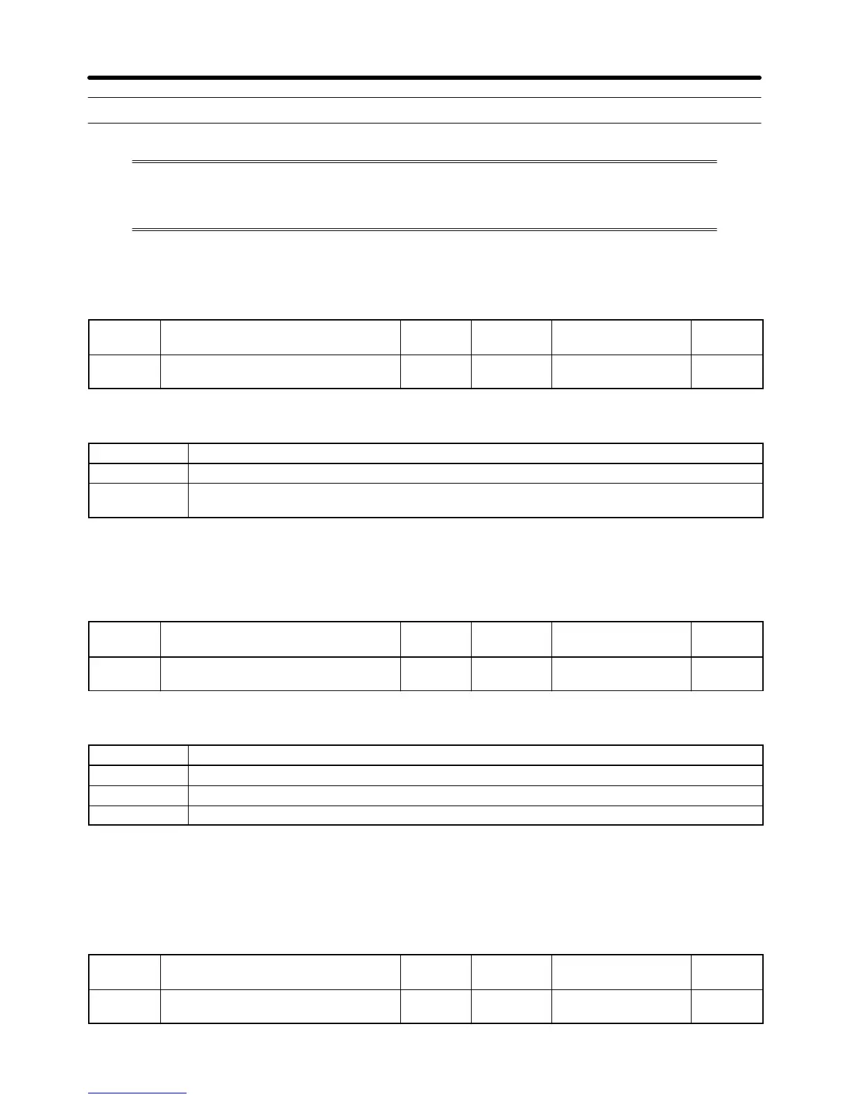
• This parameter setting is to select whether or not to detect Digital Operator connection errors.
n010
Operation Selection at Digital
Operator Interruption
Register 010A Hex Changes during
operation
No
Setting
range
0, 1 Unit of
setting
1 Default setting 0
Set Values
Value Description
0 The Digital Operator connection error is not detected (Nonfatal error)
1 The Digital Operator connection error is detected (Error output and the Inverter coasts to a
stop)
6-10-2 Motor Protection Functions (n037 and n038)
• This parameter setting is for motor overload detection (OL1).
n037
Motor Protection Characteristics Register 0125 Hex Changes during
operation
No
Setting
range
0 to 2 Unit of
setting
1 Default setting 0
Set Values
Value Description
0 Protection characteristics for general-purpose induction motors
1 Protection characteristics for Inverter-dedicated motors
2 No protection
• This parameter is used to set the electric thermal characteristics of the motor to be connected.
• Set the parameter according to the motor.
• If a single Inverter is connected to more than one motor, set the parameter to 2 for no protection. The
parameter is also disabled by setting n036 for rated motor current to 0.0. Provide overload protection
for each motor by setting up, for example, thermal relays.
n038
Motor Protection Time Register 0126 Hex Changes during
operation
No
Setting
range
1 to 60 (min) Unit of
setting
1 min Default setting 8
Advanced Operation Chapter 6

 Loading...


