3-17
Note 2. By attempting to verify the parameter set values in Inverters that are different in capacity,
“vAE” flashes for a capacity error. Press the Enter Key to continue verifying the parameter set
values. To cancel the operation, press the STOP/RESET Key.
3-2-3 Parameter Read-prohibit Selection (Prohibiting Data
Written to the EEPROM of the Digital Operator)
• To store the parameter set values in the EEPROM of the Digital Operator, set n177 for parameter read-
prohibit selection to 0. A protection error (PrE) will be detected by attempting to read the parameter set
values in the Inverter with rEd set. This protects the parameter set values in the EEPROM from
change. The PrE display is turned OFF by pressing the Mode Key.
Parame-
ter
Register Name Description Setting
range
Unit of
setting
Default
setting
Chan-
ges dur-
ing
opera-
tion
n177 01B1 Parame-
ter read-
prohibit
selection
Used to keep the data in the
EEPROM of the Digital
Operator on hold.
0: Parameter read-prohibit
(No data can be written to
the EEPROM)
1: Parameter read possible
(Data can be written to the
EEPROM)
0, 1 1 0 No
Note 1. No data can be written to n177 unless the default setting is changed. To write data to this
parameter, set n001 for parameter write-prohibit selection/parameter initialization to 4.
Note 2. The parameter setting has an effect on the Digital Operator. If the Digital Operator with the
data in the EEPROM protected is mounted to another Inverter, n117 will be set to 0 regardless
of the n117 setting in the Inverter.
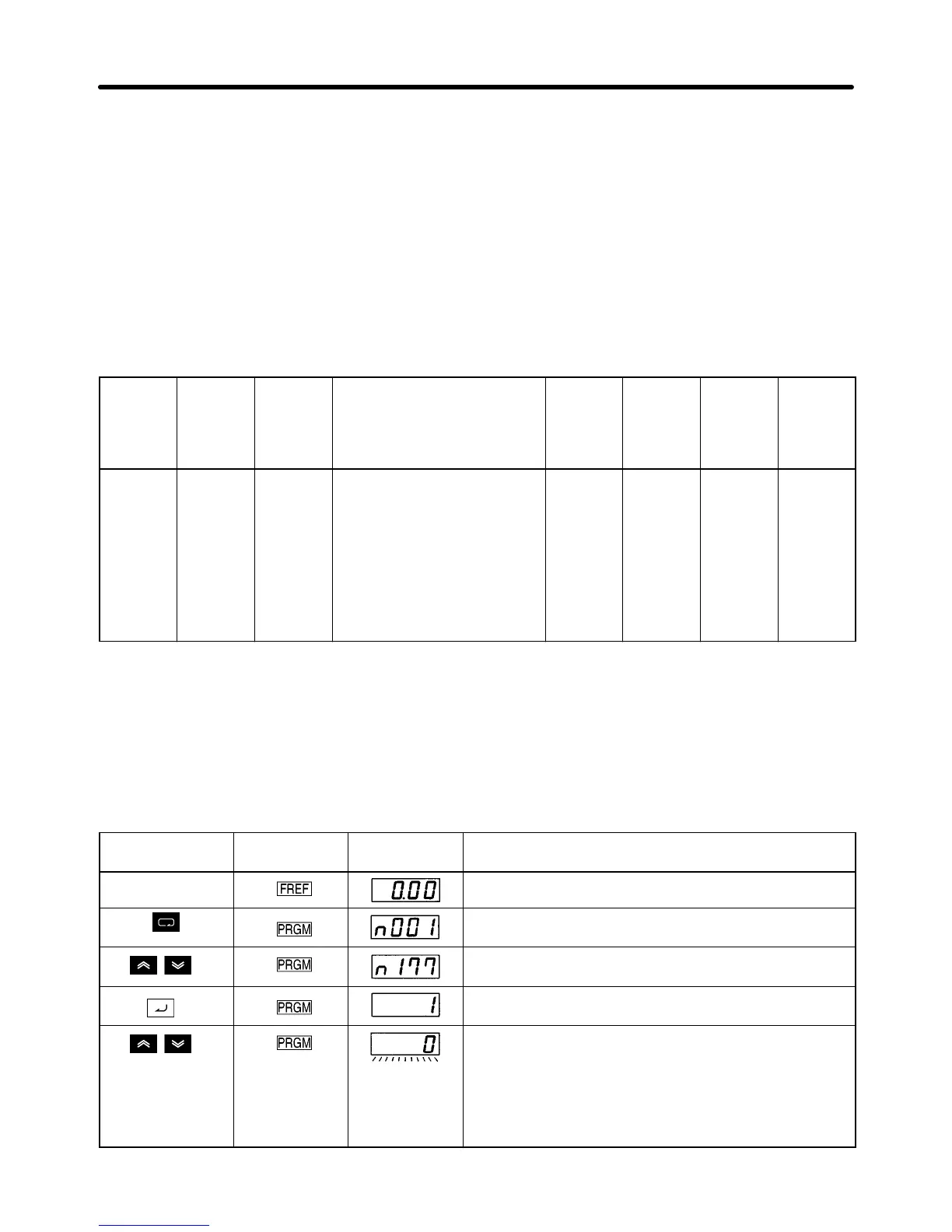
D Steps to Set Parameter Read-prohibit
Key sequence Indicator Display
example
Explanation
Power ON
Press the Mode Key repeatedly until the PRGM
indicator is lit.
Use the Increment or Decrement Key to display
“n176.”
Press the Enter Key. The present set data will be
displayed.
Use the Increment or Decrement Key to display to set
the data, during which the display flashes.
0: Parameter read-prohibit (No data can be written to
the EEPROM)
1: Parameter read possible (Data can be written to the
EEPROM)
Preparing for Operation and Monitoring Chapter 3

 Loading...


