2-14
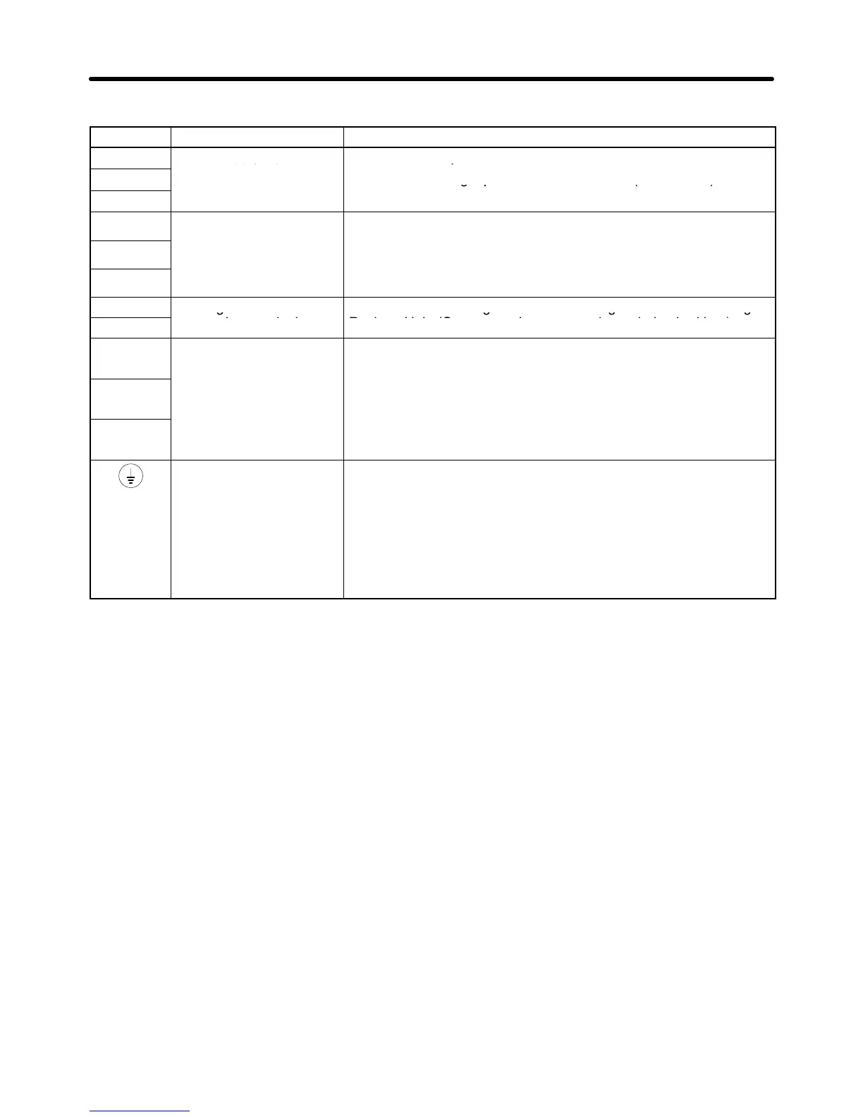
H Main Circuit Terminals
Symbol Name Description
R/L1
Power supply input
3G3MV-A2j: 3-phase 200 to 230 V AC
S/L2
terminals
3G3MV-ABj: Single-phase 200 to 240 V AC (See note 1.)
T/L3
3G3MV-A4j: 3-phase 380 to 460 V AC
U/T1
Motor output terminals 3-phase power supply output for driving motors. (See note 2.)
3G3MV A2j 3 h 200 t 230 V AC
V/T2
3G3MV-A2j: 3-phase 200 to 230 V AC
-
-
W/T3
-
-
3G3MV-A4j: 3-phase 380 to 460 V AC
B1
Braking Resistor
Terminals for attaching an external Braking Resistor or a Braking
B2
connection terminals
Resistor Unit. (Connect to detect overvoltage during braking.)
+1
Connection terminals +1
and +2:
Connect the DC reactor for suppressing harmonics to terminals +1
and +2.
+2
reactor connect
on
terminals
–
When driving the Inverter with DC power, input the DC power to
terminals +1 and –.
(Terminal +1 is a positive terminal )
–
–
DC power supply input
terminals
(Terminal +1 is a positive terminal
.
Ground terminal Be sure to ground the terminal under the following conditions.
3G3MV-A2j: Ground at a resistance of 100 Ω or less.
3G3MV-ABj: Ground at a resistance of 100 Ω or less.
3G3MV-A4j: Ground at a resistance of 10 Ω or less. To conform
to EC Directives, connect to the neutral point of the power supply.
Note Be sure to connect the ground terminal directly to the
motor frame ground.
Note 1. Connect single-phase input to both the R/L1 terminal and the S/L2 terminal.
Note 2. The maximum voltage at the output side corresponds to the power supply voltage for Inverter
input.
Design Chapter 2

 Loading...


