7-9
Note In the above communications, the default is –1 (65535) and the LSB (least-significant byte) is
converted as MSB (most-significant byte) (in the opposite direction). The CRC-16 check is auto-
matically performed by using the protocol macro function of OMRON’s SYSMAC CS-series or
C200HX/HG/HE Programmable Controllers.
H Slave Address
• The Master can communicate with a maximum of 32 Slaves over RS-422/485. A unique Slave
address is allocated to each Slave (Inverter) for communications.
• Slave addresses are within a range from 00 to 32 (00 through 20 Hex). If a DSR message is issued to
Slave address 00, the message will be a broadcast message.
Note The broadcast message is addressed to all Slaves. Only the RUN command (register 0001 Hex)
and frequency command (register 0002 Hex) can be written to the message. The Inverter receiv-
ing this message does not return a response regardless of whether or not the message is
received properly. Therefore, for measures against communications errors, the monitor function
of the Inverter should be used for checking the reception of broadcast messages.
H Function Code
• The function code is a command giving instructions of the details of processing to the Inverter.
• The following three functions codes are available.
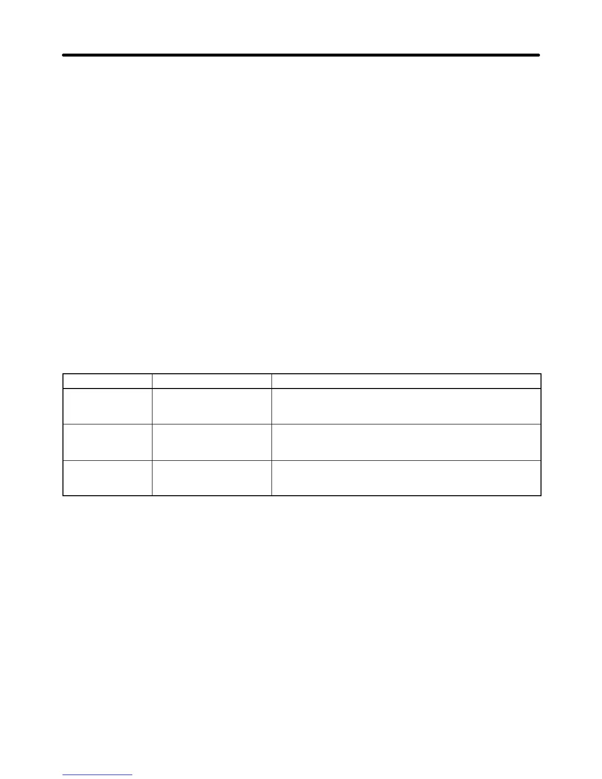
Function code Command name Description
03 Hex Data read Reads the data of the specified register number.
Consecutive data of a maximum of 16 words (32 bytes) can
be read.
08 Hex Loop-back test The DSR message is returned as a response. This
command is used for checking the status of
communications.
10 Hex Data write The attached data in the format is written to the specified
register number. Consecutive data of a maximum of 16
words (32 bytes) can be written.
Note 1. Do not use any code other than the above, otherwise the Inverter will detect a communica-
tions error and return an error message.
Note 2. The Inverter uses the same function code for the response. If an error occurs, however, the
MSB of the function code will be set to 1. For example, if an error occurs in a DSR message
with function code 03, the function code of the response will be 83.
H Communications Data
• Communications data is attached to the command. The contents and its arrangement of communica-
tions data vary with the function code. For details, refer to 7-3 DSR Message and Response.
Communications Chapter 7

 Loading...


