7-47
<l>
The length is set in the length box. Insert the length by using the Insert icon. The length is the number of
bytes of the succeeding data (W(1N + 1), 2). The length is automatically set by the CX-Protocol.
(W(1N + 1), 2)
The Inverter’s actual data is to be sent. This example selects Variable and Read R() and sets the oper-
and. Set Data to 1N + 1 because the RUN command data uses four bytes each from D + 3, D + 6, and D +
9.
Set Edit Length to 0N + 2 so that it will be set to two bytes.
7-9-5 Ladder Program
• Transfer the created protocol to the Communications Board.
• The following example describes how to control the Inverter with this protocol.
• Before using this program in your system, be sure to check the word and data memory allocations and
change them if necessary so that there will be no word or data memory duplication.
• This program will stop all communications if a communications error or fault occurs. Be sure to set
n151 for communications time-over detection selection to 0 through 2 so that the system will stop with
time-over detection.
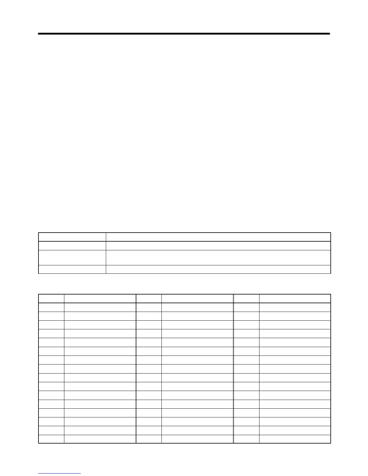
H Memory Allocations
D Starting Communications and Status Signals
Word Functions common to all Slaves
00000 Inverter control communications (continued when set to ON)
00001 Communications error output (on hold when a communications error or fault
occurs)
00002 Communications fault reset
D Inverter Control Input (Register 0001 RUN Command)
Word Slave 1 function Word Slave 2 function Word Slave 3 function
00100 RUN command 00200 RUN command 00300 RUN command
00101 Forward/Reverse 00201 Forward/Reverse 00301 Forward/Reverse
00102 External fault 00202 External fault 00302 External fault
00103 Fault reset 00203 Fault reset 00303 Fault reset
00104 Multi-function input 1 00204 Multi-function input 1 00304 Multi-function input 1
00105 Multi-function input 2 00205 Multi-function input 2 00305 Multi-function input 2
00106 Multi-function input 3 00206 Multi-function input 3 00306 Multi-function input 3
00107 Multi-function input 4 00207 Multi-function input 4 00307 Multi-function input 4
00108 Multi-function input 5 00208 Multi-function input 5 00308 Multi-function input 5
00109 Multi-function input 6 00209 Multi-function input 6 00309 Multi-function input 6
00110 Multi-function input 7 00210 Multi-function input 7 00310 Multi-function input 7
00111 Always set to 0. 00211 Always set to 0. 00311 Always set to 0.
00112 Always set to 0. 00212 Always set to 0. 00312 Always set to 0.
00113 Always set to 0. 00213 Always set to 0. 00313 Always set to 0.
00114 Always set to 0. 00214 Always set to 0. 00314 Always set to 0.
00115 Always set to 0. 00215 Always set to 0. 00315 Always set to 0.
Communications Chapter 7

 Loading...


